SBV System Series SRE - Safety Radar Equipment Instruction manual v1.2 - EN Original instructions WARNING! Anyone who uses this system must read the instruction manual to ensure safety. Read and adhere to the "Safety information" chapter in its entirety before using the system for the first time.
Copyright © 2021, Inxpect SpA All rights reserved in all countries. Any distribution, alteration, translation or reproduction, partial or total, of this document is strictly prohibited unless with prior authorization in writing from Inxpect SpA, with the following exceptions: l l l Printing the document in its original format, totally or partially. Transferring the document on websites or other electronic systems. Copying contents without any modification and stating Inxpect SpA as copyright owner.
Contents Glossary of terms iv 1. This manual 1.1 Information on this manual 6 6 2. Safety 2.1 Safety information 2.2 Conformity 8 8 11 3. Get to know SBV System Series 3.1 SBV System Series 3.2 SBV System Series control units 3.3 SBV-01 sensors 3.4 Inxpect Safety application 3.5 Fieldbus communication 3.6 Modbus communication 3.7 System configuration 12 12 14 20 21 23 24 25 4. Functioning principles 4.1 Sensor functioning principles 4.2 Detection fields 4.
Glossary of terms A Activated output (ON-state) Output that switches from OFF to ON-state. Angular coverage Property of the field of view that corresponds to the coverage on the horizontal plane. D Dangerous area Area to be monitored because it is dangerous for people. Deactivated output (OFF-state) Output that switches from ON to OFF-state. Detection distance x Depth of the field of view configured for detection field x. Detection field x Portion of the field of view of the sensor.
I Inclination Sensor rotation around the x-axis. The sensor inclination is the angle between the center of the field of view of the sensor and a line parallel to the ground. M Machinery The system for which the dangerous area is monitored. Monitored area Area that is monitored by the system. It is composed of all the detection fields of all the sensors. O OSSD Output Signal Switching Device R RCS Radar Cross-Section. Measure of how detectable an object is by radar.
1. This manual 1.1 Information on this manual 1.1.1 Objectives of this instruction manual This manual explains how to integrate SBV System Series for safeguarding machinery operators and how to install it, use it and maintain it safely. This document includes all the information as Safety Manual according to IEC 61508-2/3 Annex D. Please refer in particular to"Safety parameters" on page 79 and to "System software" on page 99.
1. This manual 1.1.4 Instruction manual updates Publication Code date DEC 2021 SAF-UMSBVBusen-v1.2 SEP 2021 SAF-UMSBVBusen-v1.1 Hardware version l ISC-B01, ISC-02 and ISC-03: 2.1 l SBV-01: 2.1 l ISC-B01, ISC-02 and ISC-03: 2.1 l SBV-01: 2.1 l l l l Firmware version ISC-B01, ISC-02 and ISC-03: 1.5.0 SBV-01: 3.0 ISC-B01, ISC-02 and ISC-03: 1.4.0 SBV-01: 1.
2. SAFETY 2.1 Safety information 2.1.1 SAFETY MESSAGES Warnings related to the safety of the user and of the equipment as envisaged in this document are as follows: WARNING! indicates a hazardous situation which, if not avoided, may cause death or serious injury. NOTICE: indicates obligations that if not observed may cause harm to the equipment. 2.1.2 SAFETY SYMBOLS ON THE PRODUCT This symbol marked on the product indicates that the manual must be consulted.
2. Safety 2.1.5 INTENDED USE SBV System Series is certified SIL 2 according to IEC/EN 62061, PL d according to EN ISO 13849-1 and Performance Class D according to IEC/TS 62998-1. It performs the following safety functions: l l Access detection function: access to a hazardous area deactivates the safety outputs to stop the moving parts of the machinery. Restart prevention function: prevents unexpected starting or restarting of the machinery.
2. Safety 2.1.8 WARNINGS FOR THE RESTART PREVENTION FUNCTION l l The restart prevention function is not guaranteed in blind spots. If required by the risk assessment, implement adequate safety measures in those areas. Machinery restarting must be enabled only in safe conditions. The button for the restart signal must be installed: o outside of the dangerous area o not accessible from the dangerous area o in a point where the dangerous area is fully visible 2.1.
2. Safety 2.2 Conformity 2.2.1 STANDARDS AND DIRECTIVES Directives 2006/42/EC (MD - Machinery) Standards 2014/53/EU (RED - Radio equipment) IEC/EN 62061: 2005, A1:2013, A2:2015, AC:2010 SIL 2 EN ISO 13849-1: 2015 PL d EN ISO 13849-2: 2012 IEC/EN 61496-1: 2013 IEC/EN 61508: 2010 Part 1-7 SIL 2 IEC/EN 61000-6-2:2019 ETSI EN 305 550-1 V1.2.1 ETSI EN 305 550-2 V1.2.1 ETSI EN 301 489-1 v2.2.3 (only emissions) ETSI EN 301 489-3 v2.1.
3. Get to know SBV System Series Contents This section includes the following topics: 3.1 3.2 3.3 3.4 3.5 3.6 3.
3. Get to know SBV System Series 3.1.3 Main components SBV System Series is composed of a control unit and up to six sensors. The Inxpect Safety application allows system operation configuration and checks. 3.1.4 Control unit - sensor communication The sensors communicate with the control unit via CAN bus using diagnostic mechanisms in compliance with standard EN 50325-5 to guarantee SIL 2 and PL d. For correct functioning, each sensor must be assigned an identification number (Node ID).
3. Get to know SBV System Series 3.2 SBV System Series control units 3.2.1 Control units supported The SBV System Series supports three different control units.
3. Get to know SBV System Series 3.2.3 Structures ISC-B01 ISC-02 ISC-03 Part A B C D E F G H I J K L Description Control unit ISC-B01, ISC-02, ISC-03 ISC-B01, ISC-02, ISC-03 ISC-B01, ISC-02, ISC-03 ISC-B01, ISC-02, ISC-03 ISC-B01, ISC-02, ISC-03 I/O terminal block System status LEDs Network parameter reset button Reserved for internal use.
3. Get to know SBV System Series Part M Description Control unit ISC-B01, ISC-02, ISC-03 CPU LEDs: on the right: status of hardware functions of the primary micro-controller l off: normal behavior l steady red: contact assistance service l only for ISC-B01 and ISC-02, on the left: status of hardware functions of the secondary microcontroller o slow flashing orange: normal behavior o other status: contact assistance service Ethernet Fieldbus port n. 1 with LEDs ISC-B01 Ethernet Fieldbus port n.
3. Get to know SBV System Series l l perform the correct input diagnostic assure the system safety level The function of each digital input must be programmed through the Inxpect Safety application. The available functions are the following: l l l l l Stop signal: optional safety function, manages a specific signal to force all the safety outputs (detection signals, if present) to OFF-state.
3. Get to know SBV System Series l l l l l l l Muting enable feedback signal: switches the selected output to ON-state in the following cases: o when a muting signal is received over the configured input and at least one group is in muting o when a muting command is received through Fieldbus communication (if available) and at least one sensor is in muting Detection signal 1: (e.g.
3. Get to know SBV System Series Idle signal is 24 V dc, periodically shortly pulsed to 0 V (pulses are not synchronous) for the receiver to detect shortcut to either 0 V or 24 V. The pulse duration at 0 V (TL) can be set at 300 μs or 2 ms through the Inxpect Safety application (Settings > Digital Input-Output > OSSD Pulse width). For details, see "Technical references" on page 78. 3.2.
3. Get to know SBV System Series 3.3 SBV-01 sensors 3.3.1 Functions The sensors perform the following functions: l l l Detect motion in their field of view. Send the motion detection signal to the control unit through CAN bus. Signal to the control unit through CAN bus the failures or faults detected on the sensor during diagnostics. 3.3.
3. Get to know SBV System Series Part D E F G Description Mounting bracket Tamper-proof screw to position the sensor at a specific angle around y-axis (pan 10° steps) Connectors for connecting the sensors in a chain and to the Tamper-proof screw to position the sensor at a specific angle around z-axis (roll 10° steps) 3.3.4 Status LED Status Steady blue Flashing blue Purple Red Meaning Sensor is working. No motion detected. Sensor is detecting motion. Not available if the sensor is in muting.
3. Get to know SBV System Series 3.4.3 Access The application can be downloaded free of charge at www.inxpect.com/industrial/tools. Some functions are password protected. The admin password can be set through the application and then saved on the control unit.
3. Get to know SBV System Series Page Function Enable access to the configuration functions. Admin password required. User Close the connection with the device and allow to connect to another device. Disconnect Change the language. 3.5 Fieldbus communication 3.5.1 Fieldbus support The safety communication on the Fieldbus interface is supported only in the ISC-B01 control unit. 3.5.
3. Get to know SBV System Series Data type Description Safe TARGET DATA Unsafe Current distance and angle of the targets detected by each sensor. For each detection field of each sensor, only the closest target to the sensor is considered.
3. Get to know SBV System Series Data type Description Unsafe TARGET DATA Unsafe Current distance and angle of the targets detected by each sensor. For each detection field of each sensor, only the closest target to the sensor is considered.
3. Get to know SBV System Series 3.7.4 Dynamic configuration through the digital inputs To activate the dynamic system configuration, one or both the digital inputs of the control unit can be used. The result is the following: If... only one digital input is used for the dynamic configuration both digital inputs are used for the dynamic configuration Then it is possible to dynamically switch between...
4. Functioning principles Contents This section includes the following topics: 4.1 Sensor functioning principles 4.2 Detection fields 4.3 Safety working modes and safety functions 4.4 Safety working mode: Both (default) 4.5 Safety working mode: Always access detection 4.6 Safety working mode: Always restart prevention 4.7 Restart prevention function: static object detection option 4.8 Features of the restart prevention function 4.9 Muting 4.10 Anti-tampering functions: anti-rotation around axes 4.
4. Functioning principles 4.2 Detection fields 4.2.1 Introduction The field of view of each sensor can be composed of up to four detection fields. Each of the four detection fields have a dedicated detection signal. WARNING! Configure the detection fields and associate them with the dual channel safety outputs according to the risk assessment requirements. 4.2.
4. Functioning principles 4.2.4 Detection distance The detection distance of the first detection field must start from the sensor. The detection distance of one field starts where the one of the previous field ends. The detection distance of one or more fields can be 0 (e.g. detection field 3). The first detection field with detection distance different from 0 (e.g detection field 1) must have a minimum detection distance of 500 ms. SBV System Series | Instruction manual v1.
4. Functioning principles 4.2.5 Detection fields dependency and detection signal generation If a sensor detects motion within a detection field, its detection signal changes status and, when configured, the related safety output is deactivated. The behavior of the outputs related to the following detection fields depends on the detection field dependency set: If... the Dependent mode is set and thus detection fields are dependent on each other Then...
4. Functioning principles In this example, detection field 1 generates a detection signal for target [A] but target [B] could not be detected. In the Inxpect Safety application, click on Settings > Sensors > Detection field dependency to set the dependency mode of the detection fields. 4.2.6 Independent detection fields: a use case It can be useful to set the detection fields as independent, for example, if there is a scheduled temporary motion of an object in a detection field.
4. Functioning principles 4.3 Safety working modes and safety functions 4.3.1 Introduction Each detection field of each sensor can perform the following safety working modes: l l l Both (default) Always access detection Always restart prevention Each safety working mode is composed of one or both of the following safety functions: Function Description Access detection The machinery is reverted into a safe status when a person enters the dangerous area.
4. Functioning principles 4.4.4 Restart timeout parameter When the system does not detect motion anymore or, with static object detection option enabled, no static object is detected, the OSSD outputs remain in OFF-state for the time set in the Restart timeout parameter. The default value is 4 s, the maximum is 60 s and the minimum is the CRT (Certified Restart timeout).
4. Functioning principles WARNING! When the restart prevention function is active the monitored area may be affected by the position and inclination of the sensors, as well as by their installation height and angular coverage (see "Sensor position" on page 42). 4.6.2 Restart timeout parameter When the system does not detect motion anymore or, with static object detection option enabled, no static object is detected, the OSSD outputs remain in OFF-state for the time set in the Restart timeout parameter.
4. Functioning principles Only when there are no restrictions does the function ensure that a person is detected when standing up [D]. SBV System Series | Instruction manual v1.2 DEC 2021| SAF-UM-SBVBus-en-v1.
4. Functioning principles 4.8.2 Types of managed restart NOTICE: it is the responsibility of the machinery manufacturer to assess if automatic restart prevention can guarantee the same level of safety as manual restart (as defined in standard EN ISO 13849-1:2015, section 5.2.2).
4. Functioning principles 4.9 Muting 4.9.1 Description Muting is an optional safety function that temporarily suspends the safety functions. Motion detection is disabled and therefore the control unit maintains the safety outputs activated even when the sensors detect motion in a detection field. The muting function must be enabled and then it is automatically activated when conditions permit it. 4.9.
4. Functioning principles 4.9.4 Enable muting signal characteristics The muting function is enabled only if both logic signals of the dedicated input meet certain characteristics. Below is a graphic representation of the signal characteristics. In the Inxpect Safety application, in Settings > Digital Input-Output it is necessary to set the parameters that define the signal characteristics. Note: with pulse duration = 0, it is sufficient that the input signals are at high logic level (1) to enable muting.
4. Functioning principles Note: a change in rotation around the y-axis cannot be detected if the movement occurs while the system is turned off. 4.10.2 Disable the anti-rotation around axes function WARNING! If the function is disabled, the system cannot signal a change in the rotation of the sensor around the axes and therefore any changes in the monitored area. See "Checks when the anti-rotation around axes function is disabled" below.
4. Functioning principles 4.11.3 Causes of masking Possible causes of masking signals are presented as follows: l l l l an object that obstructs the field of view of the sensor has been placed in the detection field. the environment in the detection field changes significantly, for example, if the sensor is installed on moving parts or if there are moving parts inside of the detection field.
4. Functioning principles 4.11.6 Checks when the anti-masking function is disabled When the anti-masking function is disabled, perform the following checks. Safety function Access detection function Schedule Before each machinery restart Restart prevention function Each time the safety outputs are deactivated Action Remove any objects that obstruct the field of view of the sensor. Reposition the sensor according to the initial installation. 4.11.
5. Sensor position Contents This section includes the following topics: 5.1 5.2 5.3 5.4 5.5 5.6 5.7 Basic concepts Sensor field of view Dangerous area calculation Calculation of range of distances Sensor position recommendations Installations on moving elements Outdoor installations 42 43 45 46 47 48 49 5.1 Basic concepts 5.1.1 Determining factors The sensor installation height and inclination depend on the optimum position of the sensor.
5. Sensor position 5.2 Sensor field of view 5.2.1 Types of field of view During the configuration phase, for each sensor it is possible to select the angular coverage of each field in a range from 10° to 100°. See "Angular coverage" on page 28. The actual detection field of the sensor also depends on the sensor installation height and inclination. See "Calculation of range of distances" on page 46. 5.2.
5. Sensor position Dimensions for the restart prevention function Note: the tolerance area dimensions described are related to the detection of humans. The tolerance area is 40° greater than the angular coverage set. Side view Top view 5.2.3 Position of the field of view The field of view is shifted of 2.5°.
5. Sensor position Top view with sensor inclination 0°. 5.3 Dangerous area calculation 5.3.1 Introduction The dangerous area of the machinery to which SBV System Series is applied must be calculated as indicated in standards ISO 13855:2010. For SBV System Series the fundamental factors for calculation are height (h) and inclination (α) of the sensor, see "Sensor position" on page 42. 5.3.
5. Sensor position 5.4 Calculation of range of distances 5.4.1 Introduction The range of detection distances for a sensor depends on the inclination (α) and the installation heights (h) of the sensor. The detection distance of each detection field (Dalarm) depends on a distance d that must be within the range of distances allowed. The formulas for calculating the distances are reported as follows. WARNING! Define the optimum sensor position according to the risk assessment requirements. 5.4.
5. Sensor position Below is an example for configuration 3, with D1 = 0.9 m and D2 = 1.6 m. 5.4.5 Calculate the real detection distance The actual detection distance Dalarm is the value to be entered on the Configuration page of the Inxpect Safety application. Dalarm indicates the maximum distance between the sensor and the object to be detected. 5.5 Sensor position recommendations 5.5.
5. Sensor position Below is an example: 5.6 Installations on moving elements 5.6.1 Introduction SBV-01 sensor can be mounted on moving vehicles or moving parts of the machinery. The characteristics of the detection field and of the response time are the same as in static installations. 5.6.2 Speed limits The detection is guaranteed only if the speed of the vehicle or of the part of machinery is from 0.1 m/s (0.66 ft/s) to 1.6 m/s (5.25 ft/s).
5. Sensor position Note: if the anti-masking function is active when the sensor is moving also, this could generate false alarms since the environment change during movement could be detected as tampering. l l Manual restart: the restart is triggered externally and only once the static object is removed from the trajectory of the moving vehicle or moving part. Application logic on PLC/control unit that permanently stops the moving part if multiple stops occur immediately after the restart of the part.
5. Sensor position 5.7.3 Recommendations for positioning the sensor Below are some recommendations for defining the sensor position: l l height above the ground: minimum 10 cm (3.9 in) suggested inclination: minimum 15° Before installing a sensor facing downwards, make sure there are neither liquids nor radar reflective materials on the floor. 5.7.4 Position not exposed to precipitation If the installation position of the sensor is not exposed to precipitation, no special precautions are required.
6. Installation and use procedures Contents This section includes the following topics: 6.1 6.2 6.3 6.4 6.5 Before installation Install and configure SBV System Series Validate the safety functions Manage the configuration Other functions 51 52 59 61 62 6.1 Before installation 6.1.1 Materials required l l l l l Two tamper-proof screws (see " Tamper-proof screws specifications" on page 81) to mount each sensor.
6. Installation and use procedures 9. "Connect the control unit to the sensors" on page 57. Note: connect the sensors to the control unit off-site if access to the connectors becomes difficult once they are installed. 10. 11. 12. 13. "Assign the Node IDs" on page 57 "Save and print the configuration" on page 58. If available, "Set the control unit Ethernet parameters" on page 58 "Validate the safety functions" on page 59. 6.2 Install and configure SBV System Series 6.2.
6. Installation and use procedures 6.2.5 Install the sensors Note: for an example of sensor installation, see "Examples of sensor installation" on page 56. 1. Position the sensor as indicated in the configuration report and fasten the bracket with two tamper-proof screws directly onto the floor or another support. NOTICE: make sure the support does not inhibit machinery commands. 2. With an Allen key, loosen the screw at the bottom to pan the sensor. 3.
6. Installation and use procedures 5. Loosen the tamper-proof screws to tilt the sensor. 6. Direct the sensor up to the desired inclination, see "Sensor position" on page 42. Note: a notch is equal to 10° of inclination. 7. Tighten the screws. 54 SBV System Series | Instruction manual v1.2 DEC 2021 | SAF-UM-SBVBus-en-v1.
6. Installation and use procedures 6.2.6 Mount bracket for z-axis rotation (roll) Note: for an example of sensor installation, see "Examples of sensor installation" on the next page. The bracket that allows rotation around the z-axis (roll) is an accessory in the package. To mount it: 1. Unscrew the screw at the bottom and remove the bracket with the sensor and the aligning ring. 2. Attach the roll bracket to the base. Use the tamper-proof screw provided with the bracket. 3.
6. Installation and use procedures 6.2.7 Examples of sensor installation NOTICE: refer to the sensor LED position to identify the sensor field of view. See "Position of the field of view" on page 44. Floor installation Wall installation (for example for access control of an entrance). Note: install the sensor so that the field of view is shifted towards the outside of the hazardous area to avoid false alarms, see "Position of the field of view" on page 44. 56 SBV System Series | Instruction manual v1.
6. Installation and use procedures Installation on the machinery. 6.2.8 Connect the control unit to the sensors Note: when replacing a sensor, in the Inxpect Safety application, click APPLY CHANGES to confirm the change. 1. With the cable validator tool (downloadable from the site www.inxpect.com/industrial/tools), decide if the control unit will be positioned at the end of the chain or inside it (see "Chain examples" on the next page). 2.
6. Installation and use procedures 3. Click Settings > Node ID Assignment. 4. Proceed according to the type of assignment: If the assignment is... manual Then... 1. Click DISCOVER CONNECTED SENSORS to display the connected sensors. 2. To assign a Node ID, click Assign for the unassigned Node ID in the Configured sensors list. 3. To change a Node ID, click Change for the already assigned Node ID in the Configured sensors list. 4. Select the SID of the sensor and confirm. 1.
6. Installation and use procedures 4. Wait until all the six LEDs on the control unit turns steady green: the Ethernet parameters are set to their default values (see "Ethernet connection (if available)" on page 79). 5. Configure the control unit again. 6.3 Validate the safety functions 6.3.1 Validation Once the system has been installed and configured, check that the safety functions are activated/deactivated as expected and that the dangerous area is monitored by the system.
6. Installation and use procedures 6.3.3 Example of access points Access points for 100° field of view 6.3.4 Validate the restart prevention function Example 1 Starting conditions Detection field dependency: Dependent mode Machinery in safe conditions l Two detection fields configured (detection field 1 and detection field 2) l Both the safety outputs (detection signal 1 and detection signal 2) deactivated 1. Stand still in detection field 1. 2.
6. Installation and use procedures 6.3.6 Validate the system with Inxpect Safety WARNING! When the validation function is active, the system response time is not guaranteed. The Inxpect Safety application is helpful during the safety functions validation phase and allows the sensors' actual field of view to be checked based on their installation position. 1. Click Validation: the validation starts automatically. 2.
6. Installation and use procedures To change... Function of inputs and outputs Muting Sensor inclination Then... Click Settings > Digital Input-Output Click Settings > Muting Loosen the side screws on the sensor and orient the sensors to the desired inclination. Sensor number and Click Configuration positioning 4. Click APPLY CHANGES. 5. Upon conclusion of transfer of the configuration to the control unit, click to print the report. 6.4.
6. Installation and use procedures 6.5.6 Change network parameters In Settings > Network Parameters change the IP address, the netmask and the gateway of the control unit as desired. 6.5.7 Change Modbus parameters In Settings > Modbus Parameters enable/disable the Modbus communication and modify the listening port. 6.5.8 Change Fieldbus parameters In Settings > Fieldbus Parameters change the F-addresses and the Fieldbus Endianness of the control unit. SBV System Series | Instruction manual v1.
7. Maintenance and troubleshooting Machinery maintenance technician The machinery maintenance technician is a qualified person, with the administrator privileges required to modify the configuration of SBV System Series through the software and to perform maintenance. Contents This section includes the following topics: 7.1 7.2 7.3 7.4 7.5 7.6 7.
7. Maintenance and troubleshooting LED S6 S1–S6 together S1–S5 together S1–S4 together At least one LED At least one LED All the LEDs All the LEDs Inxpect Safety application messages Steady red FEE ERROR, FLASH ERROR or RAM ERROR Status Steady red FIELDBUS ERROR Problem Remedy Configuration saving error, configuration not performed or memory error Communication error on the Fieldbus Reconfigure or configure the system, see "Manage the configuration" on page 61.
7. Maintenance and troubleshooting Status Flashing red. Four flashes followed by a pause ** Inxpect Safety application messages SENSOR TEMPERATURE ERROR or SENSOR POWER ERROR Problem Remedy Sensor in temperature Check the sensor connection and that error or is receiving an the cable length is within the incorrect supply voltage maximum limits.
7. Maintenance and troubleshooting 7.2 Event log management 7.2.1 Introduction The event log recorded by the system can be downloaded from the Inxpect Safety application in a PDF file. The system saves up to 4500 events, divided in two sections. In each section the events are displayed from the most recent to the least recent. Above this limit, the oldest events are overwritten. 7.2.2 Download the system log 1. Start the Inxpect Safety application. 2. Click Settings and then Activity History. 3.
7. Maintenance and troubleshooting Timestamp (absolute/relative value) An indication of the instant when the event occurred is provided. l After a new system configuration, it is provided as absolute time. Format: YYYY/MM/DD hh:mm:ss Example: 2020/06/05 23:53:44 l After a reboot of the device, it is provided as relative time from the latest boot. Format: Rel. x d hh:mm:ss Example: Rel.
7. Maintenance and troubleshooting 7.2.
7. Maintenance and troubleshooting Event Modbus connection Session authentication Validation Log download Type INFO INFO INFO INFO For further information about the events, see "INFO events" on the next page and " ERROR events (control unit)" on page 73. 7.2.7 Verbosity level There are six verbosity levels for the log. The verbosity can be set during the configuration of the system via the Inxpect Safety application (Settings > Activity History > Log verbosity level).
7. Maintenance and troubleshooting CONTROL UNIT SENSOR #k Detection exit (field #n) Detection exit 7.3 INFO events 7.3.1 System Boot Every time the system is powered up, the event is logged reporting the incremental count of the boot from the beginning of the life of the device. Format: System Boot #n Example: 0 2020/11/18 16:47:25 [INFO] CONTROL UNIT SYSTEM BOOT #60 7.3.
7. Maintenance and troubleshooting distance (in mm) and the detection angle (°). See "Verbosity level for detection access and exit events" on page 70 Format: Detection access (field #n, distance mm/azimuth°) Example: 20 2020/11/18 16:47:25 [INFO] SENSOR #1 Detection access (field #1, 1200 mm/30°) 7.3.7 Detection exit After at least one detection access event, a detection exit event related to the same field is logged when the detection signal returns to its default no-motion status.
7. Maintenance and troubleshooting 7.3.12 Session authentication The status of the session authentication and the interface used (USB/ETH) are logged. Format: Session OPEN/CLOSE/WRONG PASSWORD/UNSET PASSWORD/TIMEOUT/CHANGE PASSWORD via USB/ETH Example: 20 2020/11/18 16:47:25 [INFO] CONTROL UNIT Session OPEN via USB 7.3.13 Validation Every time a validation activity starts or ends on the device, it is logged. The interface used (USB/ETH) is logged as well.
7. Maintenance and troubleshooting Screen printing V12 sensors VUSB VREF ADC Description Sensors power supply voltage USB port voltage Inputs reference voltage (VSNS Error) Analog-digital converter 7.4.4 Peripheral error (PERIPHERAL ERROR) Error detected by diagnostics relative to the micro-controller, its internal peripherals or memories. 7.4.5 Configuration errors (FEE ERROR) Indicates that the system must still be configured.
7. Maintenance and troubleshooting 7.4.10 Input redundancy error (INPUT REDUNDANCY ERROR) Error INPUT 1 INPUT 2 Meaning Error in the redundancy on Input 1 Error in the redundancy on Input 2 7.4.11 Fieldbus error (FIELDBUS ERROR) At least, one of the inputs and outputs has been configured as “Fieldbus controlled”, but the fieldbus communication is not established or not valid. Error NOT VALID COMMUNICATION Error on the Fieldbus Meaning 7.4.
7. Maintenance and troubleshooting Screen printing V1.2 V1.8 V1 Description Micro-controller power supply voltage Internal chip power supply voltage (1.8 V) Internal chip power supply voltage (1 V) 7.5.6 Anti-tampering sensor (TAMPER ERROR) Error TILT ANGLE ERROR Sensor inclination around the x-axes ROLL ANGLE ERROR Sensor inclination around the z-axes PAN ANGLE ERROR Sensor inclination around the y-axes Meaning Note: an information in degree related to the angle is reported. 7.5.
7. Maintenance and troubleshooting Error COMMUNICATION LOST PROTOCOL ERROR POLLING TIMEOUT Meaning Impossible to communicate with the sensor Control unit and sensors have different and incompatible firmware versions Timeout on data polling 7.7 Cleaning and spare parts 7.7.1 Cleaning Keep the sensor clean and free of any work residues to prevent masking and/or poor functioning of the system. 7.7.
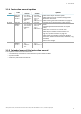
8. Technical references Contents This section includes the following topics: 8.1 8.2 8.3 8.4 8.5 78 Technical data Terminal blocks and connector pin-outs Electrical connections Parameters Digital input signals 79 82 84 91 94 SBV System Series | Instruction manual v1.2 DEC 2021 | SAF-UM-SBVBus-en-v1.
8. Technical references 8.1 Technical data PFHd 8.1.1 General specifications Detection method Inxpect motion detection algorithm based on FMCW radar Frequency Working band: 60.6–62.8 GHz Transmission power: ≤ 13 dBm Radiated power: ≤ 16 dBm mean EIRP Modulation: FMCW Detection interval From 0 to 5 m (from 0 to 16.4 ft), depending on the installation conditions. Detectable target RCS 0.
8. Technical references Fieldbus interface (if available) Ethernet based interface with different standard Fieldbus (e.g. PROFIsafe) Power supply 12 V dc ± 20%, through control unit Consumption Max 3.
8. Technical references 8.1.7 Tamper-proof screws specifications Pin Hex button head security screw d1 M4 l 10 mm (0.39 in) d2 7.6 mm (0.30 in) k 2.2 mm (0.09 in) t min 1.3 mm (0.05 in) s 2.5 mm (0.10 in) d3 max 1.1 mm (0.04 in) 8.1.8 Non tamper-proof screws specifications 8.1.6 CAN bus cables recommended specifications Hex button head screw Section 2 x 0.50 mm2 (46 AWG) power supply 2 x 0.
8. Technical references 8.1.9 Bottom screws specifications The bottom screws can be: l l cheese head button head Note: Avoid using countersunk head screws. 8.2 Terminal blocks and connector pin-outs 8.2.
8. Technical references 8.2.3 Power supply terminal block Note: connector front view. Symbol VGND Earth V+ Description + 24 V dc Note: the maximum operating temperature of the cables must be at least 70 °C. Note: use only copper wires with a minimum gauge of 18 AWG and a torque of 0.62 Nm (5,5 lbs in). 8.2.4 CAN bus terminal block Symbol + H L - Description + 12 V dc output CAN H CAN L GND Note: the maximum operating temperature of the cables must be at least 70 °C. 8.2.
8. Technical references 8.3 Electrical connections 8.3.1 Connection of safety outputs to the machinery control system Digital I/O settings (through the Inxpect Safety application) Digital input #1 Not configured Digital input #2 Not configured Digital output #1 Detection signal 1 Digital output #2 Detection signal 1 Digital output #3 Not configured Digital output #4 Not configured 84 SBV System Series | Instruction manual v1.2 DEC 2021 | SAF-UM-SBVBus-en-v1.
8. Technical references 8.3.2 Connection of safety outputs to an external safety relay Digital I/O settings (through the Inxpect Safety application) Digital input #1 Not configured Digital input #2 Not configured Digital output #1 Detection signal 1 Digital output #2 Detection signal 1 Digital output #3 Not configured Digital output #4 Not configured SBV System Series | Instruction manual v1.2 DEC 2021| SAF-UM-SBVBus-en-v1.
8. Technical references 8.3.3 Connection of stop signal (emergency button) Note: the indicated emergency button opens the contact when pressed. Note: the cables used for wiring the digital inputs must have a maximum length of 30 m (98.4 ft).
8. Technical references 8.3.4 Connection of restart signal Note: the button indicated for the restart signal closes the contact when pressed. Note: the cables used for wiring the digital inputs must have a maximum length of 30 m (98.4 ft).
8. Technical references 8.3.5 Connection of the muting input and output (one group of sensors) Note: the cables used for wiring the digital inputs must have a maximum length of 30 m (98.4 ft).
8. Technical references 8.3.6 Connection of the muting input and output (two groups of sensors) Note: the cables used for wiring the digital inputs must have a maximum length of 30 m (98.4 ft).
8. Technical references 8.3.7 Detection signal 2 connection Digital I/O settings (through the Inxpect Safety application) Digital input #1 Not configured Digital input #2 Not configured Digital output #1 Not configured Digital output #2 Not configured Digital output #3 Detection signal 2 Digital output #4 Detection signal 2 90 SBV System Series | Instruction manual v1.2 DEC 2021 | SAF-UM-SBVBus-en-v1.
8. Technical references 8.3.8 Diagnostic output connection Note: the indicated light turns on in the presence of a failure. Digital I/O settings (through the Inxpect Safety application) Digital input #1 Not configured Digital input #2 Not configured Digital output #1 Not configured Digital output #2 Not configured Digital output #3 Not configured Digital output #4 System diagnostic signal 8.4 Parameters 8.4.
8.
8.
8. Technical references 8.5 Digital input signals 8.5.1 Stop signal Part Description Detection signal 1 Both deactivate on the falling edge of, at least, one of the two input channels of the input Detection signal 2 signal. They remain in OFF-state as long as one of the two input channels remains to the low logic status (0). Stop signal CH1 Interchangeable channel. Both channels must go to low logic level (0) to set Detection Stop signal CH2 signal 1 and Detection signal 2 to OFF-state.
8. Technical references 8.5.2 Muting (with/without pulse) Without pulse SBV System Series | Instruction manual v1.2 DEC 2021| SAF-UM-SBVBus-en-v1.
8. Technical references With pulse Part Diff Muting signal (group n) CH 1 Muting signal (group n) CH 2 Muting status Dt 96 Description Less than 100 ms. If the value is greater than 100 ms, the diagnostic alarm starts and the system deactivates the safety outputs. Interchangeable channel. Without pulse: enabled as long as both channels are at a high logic level (1), and deactivated when both channels go to low logic level (0).
8. Technical references 8.5.3 Restart signal Part Description Detection signal 1 The Detection signal 1 and Detection signal 2 outputs go to ON-state as soon as the last Detection signal 2 channel has correctly completed the transition 0 -> 1 -> 0. Restart signal CH1 Interchangeable channel. Both channels of Restart signal must have a transition of logical Restart signal CH2 level 0 -> 1 ->0. The time they stay at high logical level (t) must be at least 200 ms. Dt Diff Activation delay. Less than 50 ms.
8. Technical references 8.5.4 Active dynamic configuration With one input With two inputs Part Diff Description Less than 100 ms. If the value is greater than 100 ms, the diagnostic alarm starts and the system deactivates the safety outputs. See "Dynamic configuration through the digital inputs" on page 26 for details. Dynamic configuration number Dt Activation/deactivation delay. Less than 50 ms. 98 SBV System Series | Instruction manual v1.2 DEC 2021 | SAF-UM-SBVBus-en-v1.
9. Appendix Contents This section includes the following topics: 9.1 System software 9.2 Disposal 9.3 Service and warranty 99 100 100 9.1 System software 9.1.1 Introduction The aim of this appendix is to provide and clarify the information related to the system software. It includes the information necessary for the integrator during the installation and integration in accordance with IEC 61508-3 Annex D.
9. Appendix 9.2 Disposal SBV System Series contains electrical parts. As set forth in European Directive 2012/19/EU, do not dispose of the product with unsorted urban waste materials. It is the responsibility of the owner to dispose of these products, as well as other electrical and electronic equipment, through specific waste collection facilities indicated by the government or local public authorities.
SBV System Series Instruction manual v1.2 DEC 2021 SAF-UM-SBVBus-en-v1.2 Copyright © 2021 Inxpect SpA Inxpect SpA Via Serpente, 91 25131 Brescia (BS) Italy www.inxpect.com safety-support@inxpect.