
Install Instructions

UT-SWM
UNIVERSAL THERMOSTAT
SMART WIRE MODULE
INTRODUCTION:
The UT-SWM, Universal Thermostat Smart
Wire Module is an innovative and low-cost
solution for any application where you need to
control up to five outputs and only have a
single pair of wires between two locations such
as a thermostat and HVAC system. Today’s
communicating thermostats require a
“common” wire to power the radio module and
other electronics. On average, 30% of all
homes do not have a common wire at the
thermostat. The UT-SWM uses two advanced
microprocessors; one located in the Sender
Module and the other in the Relay Receiver
Module. Signals from the device connect to the
sender Module such as a thermostat are
encoded along with checksum data to ensure
accuracy and superimposed onto the 24 volt
signal wires that transmit to the Relay Receiver
Module. The Relay Receiver Module then
decodes and verifies the binary data and turns
relays on or off to match the Sender Module
information.
IMPORTANT NOTE:
This product only works reliably with
thermostats using relays. Thermostats that
use Triacs are not recommended. Refer to
specific thermostat specifications to
confirm relay or Triac operation.
INSTALLATION INSTRUCTIONS
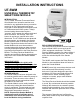
SENDER MODULE:
The Sender Module has been designed to be
as small as possible and is sealed to protect its
electronics. There are seven color coded, 6”
lead input wires on one end and two screw
terminals on the other end.
The Sender Module can be easily installed in
the wall cavity behind the thermostat after
wiring is completed. This prevents any heat
generated by the module from affecting the
thermostat’s temperature accuracy.
NOTE - Because the Sender Module is
intentionally small to facilitate ease of
installation, care should be used to not
bend the Module during installation.
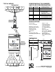
RELAY RECEIVER MODULE
The Relay Receiver Module receives its power
by an external 24VAC source such as the
HVAC equipment transformer. The Relay
Receiver Module contains five relays rated at 1
Amp maximum switching current. The relays
mimic the switched inputs of the Sender
Module.
The 24VAC used to power the Relay Receiver
Module is also transmitted down two wires to
power the Sender Module.
DO NOT power high current draw devices such
as actuators and valves directly from this
device as it has been designed to provide a
maximum of 0.5A to power field devices that
are 500mA max. When switching higher
voltages or currents, proper rated isolation
relays are required.
The Relay Receiver Module should be installed
in a cool, dry environment wherever possible.
Although the electronics are coated to protect
against moisture and dust, they are not water
resistant and should be protected from a harsh
environment.
The process of decoding and verifying the
binary data creates a very short delay in relay
response time.
RECEIVER MODULE
SENDER MODULE