Installation Guide ZP6-ESP-PRO UNIVERSAL 2-POSITION FORCED AIR ZONING SYSTEM HVAC Controls Indianapolis, IN 46237
TABLE OF CONTENTS Overview .................................................................................................................... 2 Sequence of Operation ............................................................................................... 2 Design and Installation Guidelines .............................................................................. 2 ZP6-ESP-PRO Panel Layout .............................................................................................
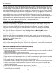
OVERVIEW The ZP6-ESP-PRO is a residential and light commercial forced air zone control systems that allows a single HVAC unit to have up to 6 separate zones. The system can be expanded to as many as 12 zones by adding 3-zone expansion panels. The panel can be used with single stage or multi-stage heat/cool equipment as well as heat pump and duel fuel systems having up to 4 stages of heating and 2 stages of cooling.
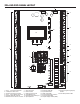
ZP6-ESP-PRO PANEL LAYOUT 2 3 AMP 3 AMP 3 4 20 18 SELECT UP DOWN 5 19 17 1 6 7 16 8 13 12 15 9 14 3 AMP 3 AMP 3 AMP 11 1. 2. 3. 4. 5. 6. Zone 1 - 6 Thermostat Terminals 3 AMP System Power Fuse 24VAC System Power Terminals Zone 1 - 6 Zone Damper Terminals Optional Night Stat Terminals ESP Static Pressure Sensor Terminals 7. 8. 9. 10. 11. 12. Sensor Terminals Fault Terminals HVAC System Terminals 3 AMP RH-RC Fuses Expansion Panel Cable Input Speed Up Button 10 13. 14. 15. 16. 17. 18.
SYSTEM WIRING WARNING! 1. Turn power off to HVAC equipment and control panel during installation to prevent serious injury from electrical shock and/or damage to the system. 2. Use extreme care when making duct openings and handling sheet metal to avoid injury. 3. Install all components in a manner that provides easy access for test, check, and startup. CAUTION! 1. Installation of this system must be in compliance with all applicable codes. 2.
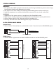
SYSTEM WIRING DS/BK Terminals The HVAC SYSTEM terminals have a DS/BK output. The DS/BK terminal is used with a variablespeed fan. Connect the HVAC equipment DS, BK, ODD, or DHUM terminal to the DS/BK terminal on the ZP6-ESP-PRO panel. Based on the DS/BK selector switch settings, this terminal will be deenergized when the number of zones calling are less than or equal to the switch selection. This will reduce the blower speed on most variable speed blowers.
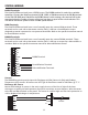
SYSTEM WIRING Return Air Sensor (Optional) Mount the return air sensor in the main return duct. Wire the sensor to the RA and RA terminals on the panel. The sensor is used to display return air temperature only. DA DA RA RA OT ZPA-DTS OT DUCT Outdoor Temperature Sensor (Optional) The outdoor temperature sensor is used for High and Low Balance Point control in heat pump and dual fuel applications but can also be used for outdoor temperature display only.
SYSTEM WIRING L L C C HVAC TERMINALS Fault Terminal The Fault Terminals are designed to send a 24 volt signal to each zone thermostat that has a fault input. This is an important feature on a heat pump system that can provide a visual alert to the user at the zone thermostat of a mechanical failure. If the equipment has a fault terminal, wire the equipment common and the fault terminal to the C and L on the panel. Zone Thermostats The Panel has inputs for six zone thermostats.
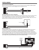
SYSTEM WIRING C C R R Y1 Y1 Y2 Y2 W1 W1 ZONE THERMOSTAT TERMINALS ZONE THERMOSTAT 3 HEAT / 2 COOL HEAT PUMP OR DUAL FUEL W2 G G O/B O/B L L If thermostat has fault input C R R Y1 Y1 Y2 Y2 W1 W1 W2 W2 G G O/B ZONE THERMOSTAT TERMINALS ZONE THERMOSTAT 4 HEAT / 2 COOL HEAT PUMP OR DUAL FUEL C O/B L L If thermostat has fault input Zone Dampers The panel has dedicated terminals for each zone damper. Dampers have three-wire, oating point actuators rated at 2.5VA.
SPS Terminals The SPS terminals 2 and 3 wire to the ZPA-SPS Static Pressure sensor. The sensor should be installed on a at surface so that the diaphragm is in the vertical position. Use the 1/4” x 36” tubing provided and connect one end to the (P1+) high pressure tting on the sensor. The other end of the tubing should be connected to the plastic sensing probe mounted in the main discharge air plenum prior to any zone dampers or duct transitions. The sensing probe is 2-1/8” x 1/4” O.D.
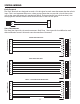
ADDING 3-ZONE EXPANSION PANELS The ZP6-ESP-EP Expansion Panel is a 3-zone module. It is mounted in its own enclosure to match the ZP6-ESP-PRO master panel. The ZP6-ESP-EP connects to the ZP6-ESP-PRO panel via an included communications ribbon connector. Another ZP6-ESP-EP can be daisy chained together in the same enclosure to provide an additional 3 zones for a total of 12. 1. When adding the expansion panel, make sure that all 24 volt power is turned off. 2.
PANEL SETUP Switch Con gurations The ZP6-ESP-PRO panel has a row of slide switches that are used to con gure the panel for the speci c equipment application. The switches also provide other control options. System Con guration Switch 1 selects the type of system. Heat Pump or Heat / Cool Switch 2 selects the type of Heat Pump. Dual Fuel or Conventional Switch 3 selects the heat pump reversing valve. B (Energized in Heating) or O (Energized in cooling Switch 4 selects the fan operation.
PANEL SETUP DS/BK Control If the HVAC system has a variable-speed fan, the DS/BK control can be used to reduce the blower speed based on the number of zones calling. Each switch has a numerical value of 1, 2 and 3. Any switch or combination of switches selected maintains the low speed fan operation until that number is exceeded.
PANEL SETUP Setting Low Limit Press the SELECT button and the Low Limit setpoint will be displayed. Use the UP or DOWN buttons to adjust the Low Limit Setpoint. The setpoint range is from 30° F to 46° F. The recommended setting is 46° F. Low Limit 46 °F SELECT UP DOWN Setting High Balance Point High Balance Point only functions in heat pump and dual fuel con guration. It is designed to prevent the auxiliary heat from coming on if the outdoor air temperature is above the High Balance Point setpoint.
PANEL SETUP Setting Low Balance Point Low Balance Point only functions in heat pump and dual fuel con guration. It is designed to prevent the compressors from coming on and switching to auxiliary heat if the outdoor air temperature falls below the Low Balance Point setpoint. Press the SELECT button to display the Low BP. Use the UP or DOWN buttons to adjust the setpoint. The setpoint range is from 0° F to 40° F.
PANEL SETUP Selecting ESP zones You can select which zones you want to apply the ESP function by toggling to the ESP Zones menu. Press the SELECT button to highlight the zone. ESP Zones ● Zone 1 ● Zone 3 ● Zone 5 SELECT ● Zone 2 ● Zone 4 ● Zone 6 UP DOWN The factory default for all zones is active ESP function as indicated by the bullet (●) next to each zone. To deselect a zone, press the UP or DOWN button until the bullet disappears.
PANEL LED DEFINITIONS AND FUNCTIONS Status LEDs PURGE - When Purge is selected, the LED will come on for 1 minute while the system goes through the purge cycle. DAS LIMIT - On when discharge air sensor is connected. Blinks when heating or cooling limit is reached. CAP CNTR - When Capacity Control is selected, the LED will come on with a call for second stage if the number of calls is less than the selected value to energize second stage and turn off when the value is reached.
PANEL LED DEFINITIONS AND FUNCTIONS Zone LEDs ZD1-ZD6 - ON when zone damper is open. Speed Up LED Speed Up - Blinks when panel is in speed up mode. 3 seconds = 1 minute in speed up mode. Pushing the Speed Up button manually turns Speed Up on and off. If left on, Speed Up mode drops out in 10 minutes.
OPTIONAL NIGHT STAT SETUP AND SCHEDULING OVERVIEW: The UT32-NS programmable touchscreen thermostat can be used for occupied and unoccupied scheduling of the ZP6-ESP-PRO panel. When wired and configured properly, the thermostat takes the place of a separate 7-day clock, night stat and override timer.
OPTIONAL NIGHT STAT SETUP AND SCHEDULING SETTING THE CLOCK AND DAY OF WEEK: It is important that the time of day and day of the week is set properly so that occupied and unoccupied programs are initiated correctly. 1. Touch and hold the Clock and the hour will flash. Tap the UP or DOWN arrow to select the correct hour. Note: PM hours are indicated by PM on the LCD. 2. Tap Clock again and the minutes will flash. Tap the UP or Down arrow to select the correct minutes. 3.
OPTIONAL NIGHT STAT SETUP AND SCHEDULING 7. Tap Program again until the hour flashes and Night is displayed on the LCD. Use the UP or DOWN arrow to set the hour start time. Note: PM hours are indicated by PM on the LCD. 8. Tap Program again until the minutes flash. Use the UP or DOWN arrow to set the minutes. 9. Tap Program again and the heating setpoint will flash. You can use the UP or DOWN arrow to change the heating setpoint or use the factory default of 62 degrees. 10.
NOTES _________________________________________________________________________________ _________________________________________________________________________________ _________________________________________________________________________________ _________________________________________________________________________________ _________________________________________________________________________________ _________________________________________________________________________________ ______________
HVAC Controls Indianapolis, IN 46237 www.iohvaccontrols.
SPECIAL ADDENDUM USING ESP ZONING PANELS WITH GAS FURNACES HAVING DIRECT SPARK IGNITION (DSI) DSI functions by creating a rapid series of high-voltage electric sparks, which means DSI controls generate electromagnetic interference (EMI) during their trial for ignition. This electronic noise can sometimes interfere with ESP zoning panels as well as other nearby electronic components and even with the ignition control itself.