User Manual DVI USB Console Extender GCE611U / GCE616U PART NO. M11225 www.iogear.
Table of Contents Introduction 4 Package Contents 4 Requirements 5 Overview 6 System Requirements 6 Rack Mounting 8 Installation 9 Grounding 9 Setting Up 10 Operation 12 The Firmware Upgrade Utility 13 Specifications 16 Troubleshooting 17 Federal Communications Commission (FCC) Statement 18 CE Compliance 18 Limited Warranty 19 Contact 19 3
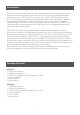
Introduction GCE611U is a DVI and USB based Console Extender with RS-232 support, it allows a user to access a DVI/USB computer system from up to 200’ (60m) away and delivers excellent resolution for up to 1920x1200 @ 60 Hz at 100’ (30 m); and 1024x768 @ 60 Hz at 200’ (60 m) . The number of computers to be accessed remotely can be expanded by deploying a compatible DVI KVM switch.
Requirements Consoles • A DVI single link or dual link DVI monitor capable of the highest resolution you will be using on any monitor in the installation.
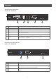
Overview Front View on Local Unit GCE611U / GCE616U 1 2 3 4 5 System Requirements No Component Description 1 DVI-D Port Connect a DVI cable from a computer to this port. 2 USB Type B Input The USB cable from your computer or USB hub plugs in here. 3 Audio Ports These mini stereo ports are for the speakers (green) and microphone (pink). 4 RS-232 Serial Port Connect the RS-232 cable from your computer into this port. 5 LEDs The unit has two LEDs to indicate the operating status.
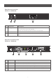
Rear View on Local Unit GCE611U / GCE616U 1 No 2 3 Component Description 1 F/W Upgrade Switch Use this switch to turn on the firmware upgrade mode. Reset the power to proceed with the firmware upgrade. Switch it off and reset the power to return to normal mode. 2 Power Jack The cable from the DC Power adapter connects here. 3 Sub / Main The 2 Cat5e cable that connects the Remote and Local Units plugs in here.
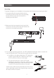
Rack Mounting For convenience and flexibility, the GCE611U and GCE616U can be mounted on system racks. To rack mount a unit do the following: 1. Using the screws provided in the Rack Mount Kit, screw the mounting bracket into the top or bottom of the unit as show in the diagram below: 2. Screw the bracket into any convenient location on the rack.
Installation Grounding To prevent damage to your installation it is important that all devices are properly grounded. 1. Use a grounding wire to ground both units by connecting one end of the wire to the grounding terminal, and the other end of the wire to a suitable grounded object. 2. Make sure that the computer that the Local Unit connects to and the monitor that the Remote Unit connects to are properly grounded. Cat5e Cables 3.
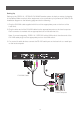
Setting Up Setting up the GCE611U / GCE616U DVI KVM Extender system is simply a matter of plugging in the cables. Make sure that all the equipment to be connected up is powered off. Refer to the installation diagram on the following page and do the following: 1. Plug the DVI KVM cable supplied with this unit into appropriate ports on the front of the Local Unit; 2. Plug the other end of the DVI KVM cable into the appropriate ports on the local computer.
4. Plug one end of the Cat5e cable into Local Unit’s Sub / Main ports. Plug the other end of the Cat 5e cable into the Sub / Main ports of the Remote Unit. 5. Connect one of the power adapters (supplied with this package with the Local Unit’s Power Jack.) 6. Plug the remote console devices (mouse, keyboard, monitor, speakers, microphone), into the corresponding ports on the Console side of the Remote Unit. 7. Connect the second power adapter (supplied with this package) with the Remote Unit’s Power Jack.
Operation Picture Ajustment The EQ switch on the unit is designed to adjust the equalization strength and improve a blinking image. The values range from 0-7 where: * 7: strongest equalization * 0: weakest equalization LED Display The GCE611U/ GCE616U Local and Remote Units have front panel LEDs to indicate their operating status, as shown in the tables, following: - Local Unit LED Indication Link (Green) - Lights steadily to indicate that the connection to the Remote unit is OK.
The Firmware Upgrade Utility GCE611U and GCE616U have a Windows-based Firmware Upgrade Utility which provides a smooth, automated process for upgrading the firmware. The new firmware upgrade packages are posted on our web site as new firmware revisions become available. Please check the web site regularly to find the latest firmware and information relating to it. Before You Begin To prepare for the Firmware Upgrade, do the following: 1.
Starting the Upgrade To upgrade your firmware: 1. Run the downloaded Firmware Upgrade Package file – either by double clicking the file icon, or by opening a command line and entering the full path to it. The Firmware Upgrade Utility Welcome screen appears: Note: The screens shown in this section are for reference only. The wording and layout of the actual screens put up by the Firmware Upgrade Utility may vary slightly from these examples. 2.
4. Click Next to perform the upgrade. If you enabled Check Firmware Version, the Utility compares the device’s firmware level with that of the upgrade files. If it finds that the device’s version is higher than the upgrade version, it brings up a dialog box informing you of the situation and gives you the option to Continue or Cancel. If you did not enable Check Firmware Version, the Utility installs the upgrade files without checking whether or not they are a higher level.
Specifications Function Connectors Console Ports Switches Emulcation Remote unit N/A 1 x USB Type A Female (White) Video N/A 1 x DVI-D Female (White) Mouse N/A 1 x USB Type A Female (White) Speakers N/A 1 x Mini Stereo Jack Female (Green) Mic.
Troubleshooting Operation problems can be due to a variety of causes. The first step in solving them is to make sure that all cables are securely attached and seated completely in their sockets. Problem Action No video Make sure that all cables are securely plugged into their sockets. Poor qulity video The video quality can be improved by adjusting the EQ switch on the GCE611U / GCE616U to increase or reduce the video signal compensation. The video quality can be improved by reducing the refresh rate.
Federal Communications Commission (FCC) Statement This equipment has been tested and found to comply with the limits for a Class A digital device, pursuant to Part 15 of the FCC Rules. These limits are designed to provide reasonable protection against harmful interference in a residential setting. This product generates, uses, and can radiate radio frequency energy and, if not installed and used as directed, it may cause harmful interference to radio communications.
Limited Warranty WE’RE HERE TO HELP YOU! NEED ASSISTANCE SETTING UP THIS PRODUCT? Make sure you: 1. Visit www.iogear.com for more product information 2. Visit www.iogear.com/support for live help and product support Warranty Information This product carries a 3 Year Limited Warranty. For the terms and conditions of this warranty, please go to http://www.iogear.com/support/warranty Register online at http://www.iogear.
© 2013 IOGEAR®