
Instruction Manual


1 2 3 4 5
1 2
3
7
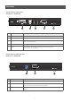
Rear View on Local Unit
GCE611U / GCE616U
No Component Description
1 F/W Upgrade Switch Usethisswitchtoturnonthermwareupgrademode.Resetthepower
toproceedwiththermwareupgrade.
Switch it off and reset the power to return to normal mode.
2 Power Jack The cable from the DC Power adapter connects here.
3 Sub / Main The 2 Cat5e cable that connects the Remote and Local Units plugs in
here.
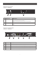
Rear View on Remote Unit
GCE611U / GCE616U
No Component Description
1 Power Jack The cable from the power adapter connects here.
2 USB The USB cable for your keyboard / mouse plugs in here.
3 Audio Ports These mini stereo ports are for the speakers (green) and microphone (pink).
4 Sub / Main The 2 Cat5e cable that connects the Remote and Local Units plugs in here.
5 DVI-D Port This DVI port is for connecting to a compatible monitor.