Installation Manual For the Edge E-Series Communications Management Unit (CMU) Amsted Digital Solutions Inc. 300 Willowbrook Lane, Suite 320 West Chester, PA 19382 USA www.amsteddigital.co +1.484.653.
Contents 1. Abbreviations & Acronyms ...................................................................................................... 3 2. Unpacking the CMU ................................................................................................................ 3 3. Powering on the CMU ............................................................................................................. 4 4. Associating the CMU to an asset .........................................................
These instructions are not designed to imply or replace any operating or safety rules. It is the responsibility of the installer to understand and follow all company safety practices. Review “Cautions” section of this manual before proceeding. 1. Abbreviations & Acronyms ADS CMU GNSS IS SCV SMIP TARA WSN Amsted Digital Solutions Inc.
3. Powering on the CMU Note: The CMU was powered down for shipping and must be powered on before TARA association and mounting to asset. 1. If the device has a red label on the top of the case, the CMU device is powered on by removing the red label and magnet. Set the magnet and red label aside for use after mounting. 2. CMUs without magnets and red labels are configured to be powered on using a Near Field Communication (NFC) reader (supplied by ADS).
4. Associating the CMU to an asset Use the TARA web site to associate the CMU to an asset. Navigate to the website below and log in using the supplied credentials https://portal.amsteddigital.net/IonxliveMassTARA/Default.aspx Note: If you receive the error message ‘Invalid User Name / Password.’, please contact Support Center at ADS to enable TARA access. North America: 1-800-621-8442 supportcenter@amsteddigital.com Europe: +1 33 1 49 07 23 65 supportcenter@amsteddigital.eu 1.
Note: The TARA application will only register CMUs that have posted messages within the last 48 hours. The CMU self-test will take more than 3 minutes if cellular signals have poor signal quality. Allow an hour for several cellular reconnection attempts if the TARA application reports serial number errors. Note: The following message should be displayed:'Success! Unit is now installed on associated to .
5. Mounting CMU device to an asset See mechanical installation drawings in Appendices A and B for specific mounting details. 6. Validating CMU Association to an Asset The CMU association to an asset may be validated using the “Detailed Status” tab. Enter the asset serial number. Enter “1” for number of messages. Click on the box labeled “Show”. Contact Support Center at ADS if messages are not reported.
7. Miscellaneous A. Other TARA Web Site Commands The TARA web site can also be used to send other TARA commands such as Uninstall, Replace, (WSM) wireless sensor monitor, Detailed Status, Change Battery. Below is a short description of each function. 1. Uninstall Used when uninstalling CMU devices from assets. Enter the serial number and asset name for the device to be uninstalled. Check the RMA check box if the device is to be returned to ADS, and press the ‘Uninstall’ button.
2. Replace Replace is no longer supported. If replacing an existing CMU on an asset, please see the Uninstall instructions in section 7.A.1. The existing CMU must be uninstalled prior to associating the new CMU. 3. WSM (wireless sensor monitor) WSM is no longer supported. 4. Detailed Status See Section 6 5. Change Battery See Appendix E 6. Inspection Inspection no longer supported B. Translations Translations available upon request. Traductions disponibles sur demande.
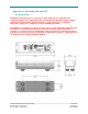
Appendix A: Mounting E4S and E5S A1. Dimensions WARNING: Mounting bracket is required for types CMU-E4S and CMU-E5S when commissioning for use in potentially explosive atmosphere. ADS part numbers 302262 and 301712, Isolation mount brackets for ExS, are approved for use in explosive atmosphere. Approval is pending for brackets 303644 and 303815.
A2. Screw-Mount Bracket Required Tools/Materials Tool Name (Part No) Description T27 Tamper Resistant Torx bit Securing CMU case to mounting plate Female square drive hex bit holder Securing CMU case to mounting plate 9.5mm [3/8”] Magnetic Drive Socket Starting self-drilling screws 4.5mm or [3/16”] Metal Drill Bit Drilling pilot holes (Optional), should use a stop collar set to 9.5mm [3/8”] or less Ratchet Head Torque Wrench set to 5.5 N-m [50 in-lb] Securing screws 9.
_____________________________________________________________________________________ 303550 Installation Manual E-Series CMU Revision Date: 14-Apr-2020 Process Owner: Engineering Confidential Revision: S Page 12 of 36
A3. Magnetic-Mount Bracket with Safety Tether Required Tools/Materials for Safety Tether Tool Name (Part No) Description Electricians’ Crimping Pliers Crimps ferrules to wire rope 1/16 inch or 1.6 mm Ferrules - 2 per tether Ferrules for wire rope 1/16 inch or 1.6 mm Wire Rope – 1.5m [5 ft] each Wire rope for safety tether 1. Choose a location (on the B-end of the railcar) for the CMU bracket that orients the CMU lid toward the sky to promote good Global Navigation Satellite System performance.
_____________________________________________________________________________________ 303550 Installation Manual E-Series CMU Revision Date: 14-Apr-2020 Process Owner: Engineering Confidential Revision: S Page 14 of 36
Appendix B: Mounting E4X, E5X, and E6X B1.
B2. Screw-Mount Bracket Required Tools/Materials Tool Name (Part No) Description T27 Tamper Resistant Torx bit Securing CMU case to mounting plate Female square drive hex bit holder Securing CMU case to mounting plate 9.5mm [3/8”] Magnetic Drive Socket Starting self-drilling screws 4.5mm or [3/16”] Metal Drill Bit Drilling pilot holes (Optional), should use a stop collar set to 9.5mm [3/8”] or less Ratchet Head Torque Wrench set to 5.5 N-m [50 in-lb] Securing screws 9.
_____________________________________________________________________________________ 303550 Installation Manual E-Series CMU Revision Date: 14-Apr-2020 Process Owner: Engineering Confidential Revision: S Page 17 of 36
B3. Magnetic-Mount Bracket with Safety Tether Required Tools/Materials for Safety Tether Tool Name (Part No) Description Electricians’ Crimping Pliers Crimps ferrules to wire rope 1/16 inch or 1.6 mm Ferrules - 2 per tether Ferrules for wire rope 1/16 inch or 1.6 mm Wire Rope – 1.5m [5 ft] each Wire rope for safety tether 1. Choose a location (on the B-end of the rail car) for the CMU bracket that orients the CMU lid toward the sky to promote good Global Navigation Satellite System performance. .
_____________________________________________________________________________________ 303550 Installation Manual E-Series CMU Revision Date: 14-Apr-2020 Process Owner: Engineering Confidential Revision: S Page 19 of 36
Appendix C: Supply Chain Visibility Tool The SCV tool uses message data stored on ADS servers to provide asset utilization, status and health information for fleet management. Amsted Digital Support Center has to set up a user account and assign a fleet name or multiple fleet names to the user account. The SCV tool has separate user guides. Use Firefox or Google Chrome to navigate to https://portal.amsteddigital.net/SCV/Home. Use the “Login” icon.
Appendix D: General Information D1. Support Center Amsted Digital Solutions provides customer service for CMU and WSN issues at their support center. A Representative can be reached at: North America: 1-800-621-8442 supportcenter@amsteddigital.com Europe: +1 33 1 49 07 23 65 supportcenter@amsteddigital.eu D2.
D3.
Appendix E: Battery Replacement Required Tools/Materials Tool Name (Part No) Description T-20 Torx driver with torque capability of 2224 in/lbs 7.2V Power Supply or Wall Wart Warning: Case can build up electrostatic charge. Clean the case by spraying with water. Do not use cloth to clean the CMU. Remove CMU to area known to be non-hazardous. ATTENTION: Le boîtier peut accumuler une charge électrostatique. Nettoyez le boîtier en pulvérisant de l'eau. N'utilisez pas de chiffon pour nettoyer le CMU.
1. Turn the CMU unit over and remove the T-20 Torx screws (ADS P/N 300842) that hold the lid in place. See Figures below. T20 Screws (300842) Figure E1 T20 Screws (300842) Figure E2 2. Carefully turn the unit over, being sure to hold the lid in place, as you do so. 3. Remove the lid, and set it aside. Inspect the enclosure and seal as directed by Appendix F: Inspection of Equipment for Return to Service. Note: Make sure the correct serial number sticker on lid stays with the correct CMU board.
Do NOT swap lids or bases. Do NOT work on more than one device at a time. Figure E3 4. Carefully lift the power cable from beside the main board and disconnect the battery. Figure E4 5. Remove the battery pack, and keep battery pack with lid for step 8. WARNING: DO NOT PLACE USED HAZARDOUS BATTERY PACKS IN THE TRASH. THESE SHOULD BE TAKEN TO A RECYLCING FACILITY THAT CAN PROPERLY DISPOSE OF THEM. ATTENTION: NE PLACEZ PAS LES PACKS DE BATTERIE DANGEREUX UTILISES DANS LA POUBELLE.
6. Connect a 7.2V power supply or wall wart to the power cable of the main board for a minimum of 5 minutes (preferably more) to pre-charge the main board and prevent errors once the new battery is connected(see Figure E5, below). Figure E5 7. Disconnect the power supply and select a new battery pack to install. WARNING: BATTERY PACK 303382: USE ONLY WITH ADS MODELS E4S and E5S. WARNING: BATTERY PACK 303406: USE ONLY WITH ADS MODELS E4X, E5X, and E6X.
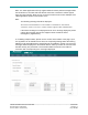
8. Navigate to the website address below and log in using the ADS supplied credentials. https://portal.amsteddigital.net/IonxliveMassTARA/Default.aspx Log in. Select the “Change Battery” tab shown below. Enter CMU Serial Number, Old Battery Serial Number and New Battery Serial Number. Figure E6 9. Install the new battery pack above into battery chamber so that the connector is facing main board, as shown in Figure E7 below. Figure E7 10. Connect the battery to the main board. 11.
12. Tuck the power cable and NFC antenna wires into the case. 13. Place the lid on the base enclosure. WARNING: ENSURE NO CABLES ARE PINCHED BETWEEN THE LID AND BASE WHEN COVERING. ATTENTION: ASSUREZ-VOUS QUE LES CÂBLES NE SONT PAS BRISÉS ENTRE LE COUVERCLE ET LA BASE LORS DE LA COUVERTURE. Figure E8 14. Inspect the enclosure and seal as directed by Appendix F: Inspection of Equipment for Return to Service. 15. Press down on the lid around the edges to insure the O-Ring is fully seated. 16.
Appendix F: Inspection of Equipment for Return to Service 1. Enclosure base and lid shall be free of cracks. 2. O-ring shall be free of cracks. If any part of the o-ring is removed, the o-ring gland must be cleaned to be free of particulates. 3. Clean top edge of enclosure base and o-ring surface with damp cloth. 4. Clean enclosure lid o-ring bump-out with damp cloth. 5. Inspect power wires. Insulation shall be free of cracks. 6 Inspect NFC antenna and wire.
Appendix G: Compliance Requirements E-Series CMU and WSN-4 series wireless sensors are produced for Amsted Digital Solutions, Inc. by: IONX, LLC 300 Willowbrook Ln, Suite 320 West Chester, PA 19382 USA Intrinsic Safety Compliance Conforms To: UL STDS 913, 60079-0, & 60079-11 Certified To: CSA STD C22.2 # 157, 60079-0, 60079-11, & 25 Electromagnetic Compliance For Part Numbers C04S2IS-NA3010 and C04X8IS-NA3010: FCC ID RI7HE910 applies.
Pour le Numéro de Pièce C04S2IS-NA3010 et C04X8IS-NA3010: Numéro de certification d'Industrie Canada IC: 5131A-HE910 s'applique. Pour le Numéro de Pièce C05S2IS-NA3010 et C05X8IS-NA3010: Numéro de certification d'Industrie Canada IC: 12436A-CMUE5A s'applique. Numéro de certification d'Industrie Canada IC: 5131A-HE910 s'applique. Pour le Numéro de Pièce C06X8IS-NA3010: Numéro de certification d'Industrie Canada IC: 12436A-CMUE6A s'applique.
For Part Numbers C04S2IS-NA3010 and C04X8IS-NA3010: Industry Canada Certification Number IC: 5131A-HE910 applies. For Part Numbers C05S2IS-NA3010 and C05X8IS-NA3010: Industry Canada Certification Number IC: 12436A-CMUE5A applies. Industry Canada Certification Number IC: 5131A-HE910 applies. For Part Number C06X8IS-NA3010: Industry Canada Certification Number IC: 12436A-CMUE6A applies. Industry Canada Certification Number IC: 5131A-HE910 applies.
Appendix H: Declaration of Conformity _____________________________________________________________________________________ 303550 Installation Manual E-Series CMU Revision Date: 14-Apr-2020 Process Owner: Engineering Confidential Revision: S Page 33 of 36
Cautions These instructions are not designed to imply or replace any operating or safety rules. It is the responsibility of the installer to understand and follow all company safety practices. WARNING In order to comply with hazardous classification, only those items specifically listed can be used and must be used only as shown. Substitution of components may affect intrinsic safety. WARNING Installation shall be carried out in accordance with the applicable code of practice by suitably trained personnel.
Avertissements Ces instructions ne sont pas conçues pour impliquer ou remplacer des règles d'utilisation ou de sécurité. Il est de la responsabilité de l'installateur de comprendre et de suivre toutes les pratiques de sécurité de l'entreprise. Instructions complètes pour utiliser CMU en français en attente. AVERTISSEMENT Afin de se conformer à la classification des matières dangereuses, seuls les éléments spécifiquement énumérés peuvent être utilisés et doivent être utilisés uniquement comme indiqué.
DOCUMENT REVISION HISTORY AND APPROVALS Document History and Approvals are electronic and stored in Arena. Amsted Digital Solutions Inc. 300 Willowbrook Lane, Suite 320 West Chester, PA 19382 www.amsteddigital.com 484.653.