iOptron®CEM40 Center-Balanced Equatorial Mount Instruction Manual Product CEM40 (#7400A series) and CEM40EC (#7400ECA series, as shown)
Please read the included CEM40 Quick Setup Guide (QSG) BEFORE taking the mount out of the case! This product is a precision instrument. Please read the included QSG before assembling the mount. Please read the entire Instruction Manual before operating the mount. You must hold the mount firmly when disengaging the gear switches. Otherwise personal injury and/or equipment damage may occur. Any worm system damage due to improper operation will not be covered by iOptron’s limited warranty.
Table of Contents Table of Contents ........................................................................................................................................ 3 1. CEM40 Introduction ............................................................................................................................... 5 2. CEM40 Overview ................................................................................................................................... 6 2.1. Parts List .................
5.4.6. Set Parking Position ................................................................................................................ 29 5.4.7. Meridian Treatment ................................................................................................................ 29 5.4.8. Set Altitude Limit ................................................................................................................... 29 5.4.9. Polar Scope Bright. ......................................................
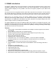
1. CEM40 Introduction The iOptron® CEM40 mount is the next generation of center-balanced equatorial mounts. This mount is incredibly eye-pleasing, and its beauty is found in more than its appearance. The functionality of the mount is superb. Weighing in at only 15.8lbs., this mount can support a payload of up to 40lbs! That's incredible! This mount also has an integrated electronic polar finder scope known as the iPolar.
2. CEM40 Overview 2.1. Parts List1 SHIPPING CONTENTS Your new CEM40 mount comes in two shipping boxes. One box contains either a CEM40 (#7400A) or CEM40EC (#7400ECA) mount head, hand controller, counterweight shaft, and accessories. The other box contains a 1.5” tripod and a 10lbs (4.5kg) counterweight.
2.2. Identification of Parts Dovetail saddle DEC gear switch Polar axis cover CW mounting housing Az. adj. knob Lat. locking screws CW locking screw Azi. locking screw Counterweight Tripod CW bar Figure 1.CEM40 mount assembly 2.3. CEM40 Mount Basic Cable Connection Figure 2. Ports on a CEM40 mount OFF/ON (O/I): Power Switch DC 12V: DC power socket to power the mount (2.1mmX5.
USB: USB port for mount-computer control and firmware upgrade 2.4. CEM40 Cable Management The CEM40 mount has a pre-wired Cable Management Panel (CMP). As shown in Figure 3, the Cable Management Panel has the following connections: Figure 3.Cable management panel 1X USB 2.0 ports with standard type A connectors for connecting accessory; 1X DC12V power outlet (2.1mmX5.5mm, center positive, max.
Figure 6. Openings for custom cable management The CMP can also be moved from the back of the dovetail saddle to the front. CMP Figure 7.
2.5. Go2Nova® 8407+ Hand Controller The Go2Nova® 8407+ hand controller (HC) shown in Figure 8 is the standard controller used on the CEM40 mount. It has an integrated heater that ensures the LCD display will work at the temperature as low as -20ºC(-4ºF). It has a large LCD screen, function, direction, and number keys on the front; a red LED reading light on the back; and a HBX (6-pin) and a RS232 serial port (4-pin) at the bottom.
STOP/0 Key: Stop the mount during GOTO. Also toggling between starting and stopping tracking. HBX (Handbox) port: connect the HC to the CEM40 mount using a 6P6C RJ11 cable. Serial port: connect the HC to a computer via a RS232 to 4P4C RJ9 cable. The pin-out of the serial port is shown in Figure 9. Figure 9. Serial port pin-out on an 8407+ hand controller 2.5.2.
8. Local Date and Time: displays the local time in a format of YY-MM-DD HH:MM:SS. 9. Mount Status: Displays the current operational status of the mount. Stop: mount is not moving; Slew: mount is moving with an arrow key is pressed or a GOTO command, such as “Select and Slew” or “Goto Zero Position”; Tracking: mount is at a tracking status. 10.
3. CEM40 Mount Assembly 3.1. CEM40 Mount Assembly NOTE: The CEM40 mount is a precision astronomical instrument. It is highly recommended that you read this entire manual and become familiar with the nomenclature and function of all components before starting assembly. WARNING: DO NOT rock the counterweight shaft rigorously. This may damage the worm/drive gear system and such damage will not be covered by warranty. STEP 1. Remove the mount head from package The mount head is shipped with the R.A.
STEP 3. Attach the mount Retract the 2x Azimuth (Azi) Adjustment Screws from both sides to leave ample space for the alignment peg to fit in between the 2 Azi Adjustment Screws. Remove the 2x Azi Locking Screws, with washers, from the mount base. Secure the mount head by tightening the Azi Locking Screws into the M6 holes on the tripod. An Allen wrench is included for convenience. Azi. Adj. Screw Allen wrench Azi. Lock Screw Azi. Lock Screw Figure 14.
Figure 16. Latitude mark window Unthread and remove the Position Bolt to its new location. Adjust the Latitude Adjustment Knob while holding the brass eyebolt until it lines up with the Position Bolt. Secure the Latitude Position Bolt. Position Bolt Figure 17. Change latitude range STEP 5. Install Counterweight (CW) Shaft Thread the CW shaft into the CW shaft mounting house. For low latitudes (<10°), a special CW mounting house is needed. (Contact iOptron for more information) Figure 18.
STEP 6. Install Counterweight(s) Before putting on CW, make sure the mount is at its zero position, i.e., CW shaft points to the ground. Disengage the R.A. Gear Switch to set the R.A. axis free before loading the CW. Remove the CW Safety Cap at the end of CW Shaft. Glide the CW over the shaft with the larger hole opening facing down. Tighten the CW Locking Screw to hold the CW in place. Place the Safety Cap back onto the shaft. Move the CW to the bottom of the shaft and tighten the CW locking Screw.
Figure 22. Losmandy dovetail saddle After switch the Stationary and Locking Blocks, make sure that the alignment mark on the Stationary Block is aligned to one of the position marks on the saddle plate. If you have a wider dovetail plate, move the Stationary Block to an outside mark. For a narrow plate, move the Stationary Block to an inside mark. The marks are located on both end of the saddle plate. STEP 8. Balance the Payload Before mounting an OTA, make sure the arrow on dovetail saddle is facing front.
Figure 24. Ports for cables Plug GPS module into the iPORT with coiled cable. When powering on, GPS ON sign should be displayed at the upper right corner of the hand controller. If you want to use the iPort for another accessory, such as WIFI adapter (iStarFi #7434), or electronic focuser (#8451/#8452), you may disconnect the GPS module after it picks up satellites signals and displays GPS OK on hand controller. (It takes about 1 to 2 minutes in normal conditions). STEP 10.
Daylight Saving Time UTC -300 Minute(s) 2019-03-09 10:19:18 Y Longitude:W071d08m50s Latitude: N42d30m32s Northern Hemisphere Set Local Time The time will be updated automatically when the GPS receiver has established its link to the satellites. In the event that the GPS module is unable to establish a link, local time can be entered manually. Use the ◄ or ► key to move the cursor _ and use the number keys to change the numbers.
numbers by 60. For example, N47.53 can be changed to N47º31'48”: 47.53º = 47º +0.53º, 0.53º=0.53x60'=31.8', 0.8'=0.8x60"=48". Therefore, 47.53º=47º31'48" or 47d31m48s. Select N/S Hemisphere The northern/southern hemisphere will be determined by your latitude coordinate, with one exception. If your are near the equator (within +/- 10°), you can choose your own N/S setting. If the polar axis is aligned to the North Celestial Pole, then set the mount to Northern Hemisphere.
Figure 25. Polar Scope Figure 26. Connect polar scope LED To perform the polar alignment: (1) Level the CEM40 mount and set it to the Zero Position. Make sure the telescope optical axis is parallel to the polar axis (R.A. axis) of the mount. If using a finder scope, adjust it to be parallel to the telescope optical axis. (2) Remove both the Polar Axis Cover and Polar Scope Cover. Thread the polar scope LED to the Polar Scope.
BrightStar Polar Alignment If you mount does not have a iPolar installed, or the pole star is not in sight, you may use two bright stars with Polar Iterate Align to do the polar alignment. (1) Level the mount and set it to the Zero Position. Align the telescope to the R.A. axis of the mount. If a finder scope is used, adjust it to be parallel to the telescope optical axis.
4. Getting Started In order to experience the full GOTO capability of GOTONOVA® technology it is very important to set up the mount correctly before observation. 4.1. Setting the Mount and Performing Polar Alignment Assemble your CEM40 mount according to Section 3.1. Make sure the mount is leveled. Turn the mount power switch on and wait for GPS receiving satellites’ signal.
4.6. Power-Down Memorization The CEM40 mount can memorize its R.A. and DEC positions if the mount power is lost during operation, even during high speed slewing. After the power is back, just do a Select and Slew to the same star when the power is lost. The mount will continue to track the star. 4.7. Turning Off the Mount When you have finished your observation, simply turn the mount power off and disassemble the mount and tripod.
5. Complete Functions of Go2Nova® 8407+ Hand Controller 5.1. Select and Slew Press the MENU button. From the main menu select “Select and Slew”. Select an object that you would like to observe and press the ENTER key. The Go2Nova® 8407+ hand controller has a database of around 212,000 objects. Use the ► or ◄ buttons to move the cursor. Use the number buttons to enter a number, or the ▼ or ▲ buttons to change a number. Hold a button to fast scroll through the list.
5.1.8. Custom R.A. and DEC Here you can go to a target by entering its R.A. and DEC coordinates. 5.2. Sync to Target This operation will match the telescope's current coordinates to the Target Right Ascension and Declination. It can be used to correct GOTO pointing error. After slewing to an object, press MENU then scroll to “Sync to Target” and press ENTER. Follow the screen to perform the sync. Using this function will re-align the telescope to the selected object.
5.3.4. Three Star Alignment The three-star alignment will further determine the cone error between the OTA and mount axis. The system will use these data to calculate the goto model. If the cone error is big enough, it is suggested to shim the OTA in DEC to minimize it. Press MENU => “Alignment” => “Three Star Alignment,” a list of alignment stars that are above the horizon is computed based on your local time and location.
Set Up Time and Site Beep Settings Display Settings Set Guiding Rates Set Tracking Rate Set Parking Position Meridian Treatment Set Altitude Limit Set Eyepiece Light Select one of three available modes: "Always On” – a beep will be heard on each button operation or mount movement; “On but Keyboard” – a beep will be heard only when the mount is slewing to the object or there is a warning message; “Always Off” – all sounds will be turned off, including the SUN warning message. 5.4.3.
WARNING: DO NOT plug your ST-4 guiding camera cable into the iOptron port or HBX port. It may damage the mount or guiding camera electronics. 5.4.5. Set Tracking Rate You can set up the mount tracking rate by selecting “Set Tracking Rate”. Set Up Time and Site Beep Settings Display Settings Set Guiding Rates Set Tracking Rate Set Parking Position Meridian Treatment Set Altitude Limit Then the user can select “Sidereal Rate”, “Lunar Rate”, “Solar Rate”, “King Rate”, and “Custom Rate”.
5.4.11. Set RA Guiding The function is for the EC version of the CEM40 only. You can turn off R.A. guiding by selecting “Inhibit R.A. Guiding” to allow the high precision encoder to correct the tracking error, or turn the R.A. guiding on by selecting “Allow RA Guiding” to allow the mount to receive guiding corrections from the guiding software. The power on default setting is “Allow RA Guiding”. 5.4.12. Language Select one of supported menu languages. Currently it has English and Chinese. 5.5.
5.7. Park Telescope This function parks the scope to one of four preset park positions. 5.8. Edit User Objects Besides various star lists available in the hand controller, you can add, edit or delete your own userdefined objects. This is especially useful for newly found comets. You can also add your favorite observation object into the user object list for easy sky surfing. Up to 60 comets and other user objects can be stored. 5.8.1. Enter a New Comet Press “MENU =>Edit User Objects” to set user objects.
Add a New Object Browse Objects Delete One Object Delete All Objects Select “Add a New Object”. A screen will be displayed asking you to Enter R.A. and DEC coordinates: Enter R.A. and DEC R.A.: 00h00m00s DEC: +00d00m00s You may enter the R.A. and DEC coordinates of the object you want to store, and press ENTER to confirm. A more useful application of this function is to store your favorite viewing objects before heading to the field. When the “Enter R.A. and DEC” screen appears, press the MENU button.
6. Maintenance and Servicing 6.1. Maintenance The CEM40 mount is designed to be maintenance free. Do not overload the mount. Do not drop the mount as this will damage the mount and / or permanently degrade GoTo performance and tracking accuracy. Use a wet cloth to clean the mount and hand controller. Do not use solvent. If your mount is not to be used for an extended period, dismount the OTAs and counterweight(s). 6.2.
Appendix A.
Appendix B. Go2Nova® 8407+ HC MENU STRUCTURE MENU Select and Slew Solar System Mercury Venus Mars Jupiter Saturn Uranus Neptune Sun Moon Deep Sky Objects Named Object Messier Catalog NGC IC PGC Caldwell Catalog Abell Catalog Herschel Catalog Stars Named Stars Double/Multi Stars Hipparcors Catalog Comets Asteroids Constellations Custom Objects User Def ined Comets Other Objects Custom R.A. and DEC Sync.
Alignment Position of Pole Star One Star Alignment Two Star Alignment Three Star Alignment Solar System Align Polar Interate Align View Model Error Clear Alignment Data Settings Set Time and Site Beep Settings Display Settings Set Guiding Rate Set Tracking Rate Sidereal Rate Lunar Rate SolarRate King Rate Custom Rate Set Parking Position Horizon Position 1 Zenith Position 1 Horizon Position 2 Zenith Position 2 Current Position Custom Parking Pos.
Electric Focuser PEC Options PEC Playback Record PEC PEC Data Integrity Park Telescope Edit User Objects User Def ined Comet Add a New Comet Browse Comets Delete a Comet Clear All Comets Other Objects Add a New Object Browse Objects Delete an Object Clear All Objects Firmware Inf ormation Zero Position Goto Zero Position Set Zero Position Search Zero Position 37
Appendix C. Polar Alignment using iPolar Electronic PolarScope Connect iPolar to a PC and Download iPolar Software (1) (2) (3) (4) (5) Connect the iPolar Electronic Polar Scope to your PC USB port; The iPolar driver will be automatically installed if it is the first time connecting to the computer; You should see “iOptron iPolar” under Camera catalog in computer Device Manager; Goto www.ioptron.com to download iPolar software and save on your computer; The iPolar software needs Windows 7, 8.
Appendix D. Gear Meshing Adjustment CEM40 gear is designed adjustable by customer although in most cases not necessary. If you experienced DEC/RA motor stall occasionally, or there is free play between the worm and gear, follow this instruction to adjust the gear meshing. Tool needed: 2mm and 3mm hex keys. To Adjust DEC Gear: Disengage DEC gear switch Rotate DEC saddle to exposure the small hole (3mm in diameter) that is blocked by the dovetail saddle.
Adjust the gear adjustment screw on the side inside the large hole by using the 3mm hex key. Turn counterclockwise to loosen the meshing or turn clockwise to tighten the meshing. If the motor stalls or the mount does not tracking smoothly, most likely the meshing is too tight. You may loosen it by about 1/8 turn (or less for tracking). Tighten the set screw in the small hole to LOCK the gear screw (important) before test the mount. Adjust again if needed, but no more than ¼ turn in total.
Appendix E. Firmware Upgrade The firmware in the 8407+ Hand Controller and control boards can be upgraded by the customer. Please check iOptron’s website, www.iOptron.com, under Support Documents of the CEM40 product page. The mount firmware is upgraded via USB port on the mount. The hand controller firmware is upgraded via RS232 port on HC.
Appendix F. Computer Control a CEM40 Mount The CEM40 mount can be controlled by a SmartPhone, a tablet or a computer. It is supported by two types of computer connections: Connect to a computer via USB port on the mount main board using a USB cable. You may need to install a FTDI USB to RS232 VCP driver (https://www.ftdichip.com/Drivers/VCP.htm). The mount can be controlled via ASCOM protocol (Windows OS), or directly by some software, such as Sky Safari (Mac OS).
Appendix G.
Messier Catalog This table is licensed under the GNU Free Documentation License.
Named Stars 1 2 3 4 5 6 7 8 9 10 11 12 13 14 15 16 17 18 19 20 21 22 23 24 25 26 27 28 29 30 31 32 33 34 35 36 37 38 39 40 41 42 43 44 45 46 47 48 49 Acamar Achernar Achird Acrab Acrux A Acrux B Acubens Adhafera Adhara Adid Australis Ahadi Al Dhanab Al Dhibain Prior Al Kab Al Nair Al Nair al Baten Al Niyat(Sigma) Al Niyat(Tau) Albaldah Albali Albireo Alchiba Alcor Alcyone Aldebaran Alderamin Alfirk Algenib Algenubi Algieba Algiedi Secunda Algol Algorab Alhakim Alhena Alioth Alkaid Alkalurops Alkes Almaaz A
197 198 199 200 201 202 203 204 205 206 207 208 209 210 211 212 Proxima Centauri Rasalas Rasalgethi Rasalhague Rastaban Regor Regulus Rigel Rigel Kentaurus A Rigel Kentaurus B Ruchbah Rukbat Rukh Rutilicus Sabik Sadachbia 213 214 215 216 217 218 219 220 221 222 223 224 225 226 227 228 Sadalbari Sadalmelik Sadalsuud Sadr Saiph Sargas Scheat Schedar Seginus Shaula Sheliak Sheratan Sirius Skat Spica Suhail 229 230 231 232 233 234 235 236 237 238 239 240 241 242 243 244 46 Sulafat Syrma Talitha Tania Aust
Modern Constellations No.
Double/Multi Stars No.
No.
No.
No.
IOPTRON TWO YEAR TELESCOPE, MOUNT, AND CONTROLLER WARRANTY A. iOptron warrants your telescope, mount, or controller to be free from defects in materials and workmanship for two years. iOptron will repair or replace such product or part which, upon inspection by iOptron, is found to be defective in materials or workmanship. As a condition to the obligation of iOptron to repair or replace such product, the product must be returned to iOptron together with proof-of-purchase satisfactory to iOptron. B.