
User's Manual


14
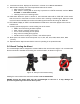
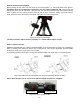
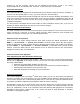
STEP 3. Attach the mount
Retract the 2x Azimuth (Azi) Adjustment Screws from both sides to leave ample space for the
alignment peg to fit in between the 2 Azi Adjustment Screws. Remove the 2x Azi Locking Screws, with
washers, from the mount base. Secure the mount head by tightening the Azi Locking Screws into the
M6 holes on the tripod. An Allen wrench is included for convenience.
Figure 14. Attach the mount
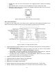
Level the mount by adjusting the tripod legs. Use the build-in Bubble Level Indicator or an external
leveler for this purpose.
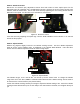
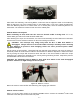
STEP 4. Adjust latitude
Without any payload, slightly loosen the 4x Latitude Locking Screws. Use the Latitude Adjustment
Knob to set the correct latitude value, as displayed in the Latitude Mark Window. Insert the Allen
wrench into the Latitude Adjustment Knob for more turning torque.
Figure 15. Adjust latitude
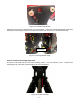
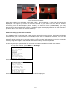
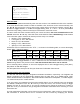
Two latitude ranges, 0~35° and 25~60°, can be set up for the mount head. To change the latitude
range from one to the other, both the Latitude Position Bolt and the Latitude Locking Screws need to
be moved to the correct locations (see photos below).
Loosen the Latitude Locking Screws just enough to adjust the latitude setting to 30°. Move the Latitude
Locking Screws with washers (one on each side) to the new locations revealed, do not tighten them just
yet.
Allen wrench
Azi. Adj. Screw
Lat. Lock Screw
Lat. Adj. Knob
Lat. Mark
Azi. Lock Screw
Azi. Lock Screw