
Installation Guide
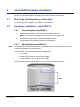
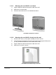
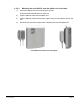
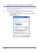
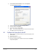
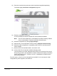
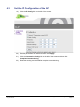
Table Of Contents
- nano3GAP Installation Manual
- 1 Introduction
- 2 Installation Requirements
- 3 nano3GAP Hardware Installation
- 4 Deployment Commissioning of the nano3GAP
- 5 Configuration of the nano3GAP-4 from the OMC-R
- 6 Troubleshooting
- 7 nano3GAP and PSU Regulatory Information
- 8 Appendices
- 8.1 Appendix A - Example AP Configuration File
- 8.2 Appendix B - Licenses and Copyright Notices
- 8.2.1 asn1c
- 8.2.2 bash
- 8.2.3 BusyBox
- 8.2.4 cramfs
- 8.2.5 dropbear
- 8.2.6 glibc
- 8.2.7 gmp
- 8.2.8 ipkg
- 8.2.9 iproute2
- 8.2.10 iptables
- 8.2.11 libcurl
- 8.2.12 libgcc
- 8.2.13 libpcap
- 8.2.14 libxml2
- 8.2.15 Linux Kernel
- 8.2.16 mtd.utils
- 8.2.17 ncurses
- 8.2.18 NTP daemon
- 8.2.19 pcre
- 8.2.20 procps
- 8.2.21 SSL Stack
- 8.2.22 StrongSwan
- 8.2.23 TCL
- 8.2.24 tcpdump
- 8.2.25 thttpd
- 8.2.26 U-Boot
- 8.2.27 zlib
- 8.2.28 General Licenses

nano3GAP Installation Manual nano3GAP Hardware Installation
© ip.access Ltd Page 8
3 nano3GAP Hardware Installation
This section documents the procedure used to install the nano3GAP-4 hardware and
physical connections together with applying the base software configuration.
3.1 Warnings and Regulatory Information
For all warnings and regulatory information, refer to section 7.
3.2 Hardware Installation - nano3GAP-4
3.2.1 Unpacking the nano3GAP-4
1) Unpack the nano3GAP-4, the stand and the POE splitter unit.
Note: No screws are supplied to mount the AP or the splitter unit.
2) Check that the items have not been damaged in transit.
Any damaged units should be returned to the supplier.
3.2.2 Mounting the nano3GAP-4
Note: The nano3GAP-4 should be installed in a position so that it is at least 2m away from the
area where handsets are normally used.
The nano3GAP-4 can be mounted in the following ways:
• on a stand
• directly onto the wall at or above head height
• onto the splitter unit at or above head height
The nano3GAP-4 has 2 holes at the back for the latter two mounting options: