
Data Sheet
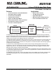


4-Level FSK Modem Data Pump Page 3 of 47 MX919B PRELIMINARY INFORMATION
©2001 MX•COM, INC. www.mxcom.com Tele: 800 638 5577 336 744 5050 Fax: 336 744 5054 Doc. # 20480170.003
4800 Bethania Station Road, Winston-Salem, NC 27105-1201 USA All trademarks and service marks are held by their respective companies.
4.5.2.17 T4S: Transmit 4 Symbols ............................................................................................... 20
4.5.2.18 RESET: Stop any current action .................................................................................... 20
4.5.2.19 Task Timing .................................................................................................................... 20
4.5.2.20 RRC Filter Delay............................................................................................................. 21
4.5.3 Control Register .................................................................................................................... 22
4.5.3.1 Control Register B7, B6: CKDIV - Clock Division Ratio ................................................. 22
4.5.3.2 Control Register B5, B4: FSTOL - Frame Sync Tolerance to Inexact Matches............. 22
4.5.3.3 Control Register B3, B2: LEVRES - Level Measurement Modes .................................. 23
4.5.3.4 Control Register B1, B0: PLLBW - Phase-Locked Loop Bandwidth Modes .................. 23
4.5.4 Mode Register....................................................................................................................... 24
4.5.4.1 Mode Register B7: IRQEN - IRQ Output Enable ......................................................... 24
4.5.4.2 Mode Register B6: INVSYM - Invert Symbols................................................................ 24
4.5.4.3 Mode Register B5: RXTX/ - Tx/Rx Mode ...................................................................... 24
4.5.4.4 Mode Register B4: RXEYE - Show Rx Eye.................................................................... 25
4.5.4.5 Mode Register B3: PSAVE - Powersave........................................................................ 25
4.5.4.6 Mode Register B2, B1, B0.............................................................................................. 25
4.5.5 Status Register ..................................................................................................................... 26
4.5.5.1 Status Register B7: IRQ - Interrupt Request .................................................................. 26
4.5.5.2 Status Register B6: BFREE - Data Block Buffer Free.................................................... 26
4.5.5.3 Status Register B5: IBEMPTY - Interleave Buffer Empty............................................... 26
4.5.5.4 Status Register B4: DIBOVF - De-Interleave Buffer Overflow ....................................... 26
4.5.5.5 Status Register B3: CRCERR - CRC Checksum Error.................................................. 27
4.5.5.6 Status Register B2, B1, B0............................................................................................. 27
4.5.6 Data Quality Register............................................................................................................ 27
4.6 CRC, FEC, and Interleaving............................................................................................. 27
4.6.1 Cyclic Redundancy Codes.................................................................................................... 27
4.6.1.1 CRC1 .............................................................................................................................. 27
4.6.1.2 CRC2 .............................................................................................................................. 28
4.6.1.3 Forward Error Correction................................................................................................ 28
4.6.1.4 Interleaving ..................................................................................................................... 28
4.7 Transmitted Symbol Shape.............................................................................................. 28
5. Application................................................................................................................... 30
5.1 Transmit Frame Example................................................................................................. 30
5.2 Receive Frame Example.................................................................................................. 33
5.3 Clock Extraction and Level Measurement Systems.......................................................... 36
5.3.1 Supported Types of Systems................................................................................................ 36
5.3.2 Clock and Level Acquisition Procedures with RF Carrier Detect ......................................... 36
5.3.3 Clock and Level Acquisition Procedure without RF Carrier Detect ...................................... 36
5.3.4 Automatic Acquisition Functions........................................................................................... 37
5.4 AC Coupling.....................................................................................................................37
5.5 Radio Performance.......................................................................................................... 39
5.6 Received Signal Quality Monitor ...................................................................................... 40