
User Guide

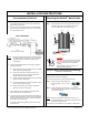


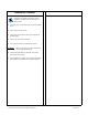
Table Of Contents
- Mobile Radio System Installation Guide
- Mobile Radio Illustration
- Installation Overview
- Installation Instructions
- Pre-Installation Guidelines
- Mounting the Mobile Radio
- Serial Cable Connection and Routing
- EMI Filter Installation
- Radio Power Supply Installation
- MDC Power Supply Installation
- Carling Switch Installation (DPST Heavy Duty Toggle)
- Delay Timer Installation
- Antenna Installation
- VIU Connections
- Mobile Radio Testing
- Installation Checklist
- Vehicle Unit Wiring Interconnection Layout
- Mobile Antenna Distance Matrix
- Diversity Antenna Mobile Installation Detail (Typical Install)
- Vehicle Unit Wiring Interconnection Layout (with VIU)
- Vehicle Unit Wiring Interconnection Layout (Data 911 with VIU)

~\Technical Documentation\Install_Guides\MR-Guide\2-May-02 Page 8 of 15
Antenna Installation
NOTE: Two (2) antennas are mounted and installed on the roof
of the vehicle using specific measurements for distance.
To mount and install the antennas, perform the following steps:
Step 1 Install antennas (see sample drawing DT450-10-0201
and Fig. 11 below).
The separation distance between the two (2) antennas
is 19”. The preferred is 31.25”.
The minimum distance of the RX2 antenna from the light
bar is 3.2”.
Observe correct separation between antennas (refer to
the Mobile Antenna Distance Matrix for midpoint
distance calculations on page 12) and minimum Near
Field Exclusion Zone (NFEZ) for proper diversity
reception operation.
Step 2 Cut a mounting hole in the roof of the vehicle using an
electric drill or hole saw.
NOTE
: The antenna-mounting hole provides ground
connection to the antenna. Ensure that a
metal-to-metal connection between the
antenna shields exists.
Figure 11
NOTE
: Figure 11 represents the recommended front-to-rear
antenna installation. The receiver antenna (RX2) should
be the antenna nearest to the light bar.
Step 3 All antenna mounts must be environmentally tight.
Install or use O-rings to seal the antenna base to the
rooftop of the vehicle.
Step 4 Route the coaxial cables to the radio through one of the
hollow spaces in the roof supports into the trunk
compartment where the radio is mounted.
NOTE: Both antennas should be checked and tested to ensure
they are functioning properly.
If these installation guidelines are followed, it is safe for
persons to stand at a distance no less than 39 inches
from the antennas.
NOTE
: The following test is performed without any power, thus
can be performed immediately after the installation of the
coax and antenna, following the installation of the N-type
connector on the coax.
To measure Return Loss, perform the following steps:
Step 1 Select one of the following Antenna Analysts to perform
the test:
•
450 to 508 MHz installations, use the 140-525
Analyst
•
806 to 960MHz installations, use the CellMate
Analyst
Step 2 Connect the antenna to be tested to the Antenna
Analyst.
Step 3 Turn on the Antenna Analyst and the Return Loss
(RETL) is displayed in dB to the left of the Voltage
Standing Wave Ratio (VSWR) curve.
NOTE
: The Return Loss Specification is –14 dBm or
greater (with good antennas the typical range
will be between –14 and –28).
To measure the Voltage Standing Wave Ratio (VSWR) Reflected
Power, perform the following steps:
Step 1 After selecting the appropriate Analyst and connecting
the antenna to be tested, press F1 to access the
Analyst Menu.
Step 2 Press F1 again to access the Display (DSPLY) menu,
which lists the modes.
Step 3 Press F2 to select the VSWR display mode. Plotting
will resume and the VSWR value is highlighted.
NOTE
: The VSWR Reflected Power Specification is
1.6 watts or less.
To measure Return Loss or VSWR on an unterminated length of
coax, perform the following steps:
Step 1 Connect the antenna to be tested to the appropriate
Antenna Analyst.
Step 2 Turn on the Antenna Analyst and the Return Loss is
displayed in dB to the left of the VSWR curve.
NOTE
: To switch from the RETL mode to VSWR
mode, refer back to the previous set of
instructions.
Step 3 Divide the result by two (2).
1
2