
User Guide

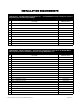
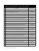
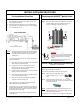


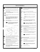

Table Of Contents
- Mobile Radio System Installation Guide
- Mobile Radio Illustration
- Installation Overview
- Installation Instructions
- Pre-Installation Guidelines
- Mounting the Mobile Radio
- Serial Cable Connection and Routing
- EMI Filter Installation
- Radio Power Supply Installation
- MDC Power Supply Installation
- Carling Switch Installation (DPST Heavy Duty Toggle)
- Delay Timer Installation
- Antenna Installation
- VIU Connections
- Mobile Radio Testing
- Installation Checklist
- Vehicle Unit Wiring Interconnection Layout
- Mobile Antenna Distance Matrix
- Diversity Antenna Mobile Installation Detail (Typical Install)
- Vehicle Unit Wiring Interconnection Layout (with VIU)
- Vehicle Unit Wiring Interconnection Layout (Data 911 with VIU)

~\Technical Documentation\Install_Guides\MR-Guide\2-May-02 Page 9 of 15
400−512ΜΗζ ∗∆ΙςΕΡΣΙΤΨ ΜΟΒΙΛΕ ∆ΑΤΑ ΡΑ∆ΙΟ
VIU Connections
INVADR
Mobile Radio Testing
If connecting a VIU, an additional serial cable is required.
10-ft serial cable (
IPMN p/n: 156-0245-010)
included with VIU
To connect the serial cables, perform the following steps:
Step 1 Attach 20-ft serial cable male connector
(DB9M)
to the
radio.
Step 2 Route the female connector
(DB9F)
to the driver
compartment and connect to the serial port located on
the rear of the VIU near the microphone hang up clip.
Step 3 Attach the 10-foot serial cable male connector
(DB9M)
to
the other serial port located on the rear of the VIU.
Step 4 Route the female connector
(DB9F)
serial cable to the
serial port located on the rear of the MDC.
Figure 12
To connect the VIU power supply, perform the following steps:
Step 1 Route the VIU’s power supply cable from the driver
compartment to the trunk compartment.
Step 2 Connect the black
(#18 AWG)
wire from the VIU power
cable to the negative (-) terminal on the EMI Noise Filter.
Step 3 Attach the red
(#18 AWG)
wire of the VIU power cable via
the 3 AMP in-line fuse to the radio connection on the EMI
Noise Filter.
Figure 13
1. To verify that the
INVADR
tm
Mobile Radio setup works
properly, use a wattmeter and a service monitor.
NOTE
: If a wattmeter and a service monitor are not
available, begin test from Step 3 through 6 and 10
through 12.
2. Connect the wattmeter between the radio and the coax
connector.
3. Connect the radio to a computer with the IPMobileNet IP
Message Utility program loaded. See the following
documents for further details:
INVADR
VIU Forwarding – IPMN p/n: 516-80309
INVADR
Mobile Data Computer for Communication
with the INVADR
Mobile Radio – IPMN p/n: 516-80310
4. Double click on the SLIP2INVADR icon to start the dial-up
connection.
5. Double click on the IP Message shortcut.
6. In the To: field, enter the radio’s IP address and click on the
Send button and the radio’s configuration will list in the upper
message screen.
7. Tune the service monitor to the assigned transmitter
frequency.
8. On the computer, in the lower message screen of the IP
Message Utility, type unlock=password (entering the
appropriate password to unlock the radio).
9. In the lower message screen, type x=2000, 19 and click on
the Send button to key the transmitter and measure the
forward power and reflected power.
10. Measure the transmitted frequency and the modulation level.
11. At the computer, using the IP Message Utility program, in the
lower message window, type V and click on the Send button
to enable verbose.
12. Ping the IPNC via MS-Dos using the following command:
Ping (IPNC IP address) –n 20 –l 500
Performance statistics showing TX data, RX data quality (DQ)
and signal levels (RSSI) will display on the IP Message
window.