
User Manual
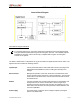
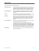
Table Of Contents

SECTION 1: THEORY OF OPERATION
IP4HPVGPS-MRFCCRpt.doc Page 4
The RF circuit board contains the following sections:
Transmit Processing Circuitry that amplifies the analog audio signal from the modem and uses it
to modulate the voltage controlled oscillator (VCO) and 10 MHz reference
oscillator in the injection synthesizer section. Modulating the VCO and
reference oscillator simultaneously results in a higher quality FM signal.
Injection Synthesizer Provides programmable, ultra stable signals for the radio. Synthesizer
incorporates phase lock loop technology used for both receiving and
transmitting.
Injection In the receive mode, the synthesizer provides a local oscillator signal of 45
MHz above or below the selected receive channel frequency.
Transmitter Consists of an exciter and power amplifier module. The transmitter covers
the various frequency bands in segments. A different power amplifier
module is required for each segment. The transmitter circuitry includes a
T/R switch switching the antenna between transmitter and receiver 1
(TX/RX1).
Receiver 1/Receiver 2 Required to support the mobile DRS; two (2) discrete receivers are tuned
to the same channel and use two (2) antennas.
The receivers are double-conversion superheterodyne with a first
Intermediate Frequency (IF) of 45 MHz and a second IF frequency of 455
KHz. Each receiver consists of bandpass filters, an RF amplifier, a MMIC
mixer, crystal filters, and a one-chip IF system. The injection synthesizer
provides the first local oscillator signal. Outputs from each receiver include
RSSI and analog audio for the baseband routing circuitry and modem.
Power Supply Consists of circuitry that derives the various operating voltages for the RF
portion of the mobile radio.