
User Manual
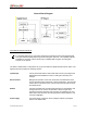
Table Of Contents

SECTION 1: THEORY OF OPERATION
IP4HPVGPS-MRFCCRpt.doc Page 7
Receiver 1 Front-End
This section contains components that include several RF Bandpass filters, a low-noise amplifier, and a
MMIC mixer.
Incoming signals pass through one (1) pre-selector filter (FLT7) that selectively provides a high degree of
out-of-band signal rejection. A low-noise amplifier (U3) amplifies the selected signals and is followed by
an image and noise reject filter (FLT8). The output from FLT8 passes through a mixer (U4). U4 is a
MMIC mixer which mixes the receive injection (RXINJ1) signal from the synthesizer and the RF signal
from the antenna to produce a 45 MHz IF signal. This 45 MHz signal passes through crystal filters (FLT3
and FLT4) to the Receiver 1 IF section to provide the bulk of the Receiver’s selectivity.
Receiver 2 Front-End operates identical to Receiver 1 Front-End.
Receiver 1 IF
The major contributor of the IF subsystem (U33) a complete 45 MHz superheterodyne receiver chip
incorporating a mixer/oscillator, two limiting intermediate frequency amplifiers, quadrature detector,
logarithmic received signal strength indicator (RSSI), voltage regulator and audio and RSSI op amps.
Incoming 45 MHz signals appearing at RX1_45MHz pass through the low-voltage high performance
monolithic FM IF system. Within U33, the signals pass through a simple LC filter and are boosted by the
RF amplifier. The output of the RF amplifier drives a mixer. A crystal oscillator is controlled by crystal Y4
and provides the injection frequency for the mixer. The mixer output passes through a 455 KHz ceramic
filter (FL6). It is then amplified and passed through another ceramic filter (FL5) to a second gain stage.
The IF output drives a quadrature detector. The phase shift elements for the detector are C123 and
FLT5. The RSSI detector converts the AGC voltage generated inside the chip into a DC level
corresponding logarithmically to the signal strength. The Diversity Reception Controller uses BRSSI1 to
select the receiver with the best quality signal.
The audio is amplified by an op amp (U19C) and delivered to the power and analog ground circuitry via
the RXMOD1 output. High frequency de-emphasis is provided by a filter consisting of a resistor and a
capacitor. In order to match the audio signal levels with the other circuitry, a gain control is included. A
pot (R81) is necessary to adjust gain.
Receiver 2 IF operates identical to Receiver 1 IF.
Transmit Modulation
The analog circuitry in this section modulates the Transmitter. The data-bearing audio signal from the
modem appears at TXMOD. The audio is amplified by op amp (U70D). The output of U70D drives two
(2) amplifiers (U70B and U70C).
The transmitter uses dual-point modulation meaning the modulation is applied both to the VCO as well as
the reference oscillator (VCTCXO).
The upper amplifier (U70B) has adjustable gain. The output drives op amp (U70A), which inverts the
phase of the signal. Upon the start of a transmission, the modulating signal passes through to the
VCTCXO reference oscillator in the synthesizer. Some makes of VCTCXO oscillators do not require the
modulation signal to be inverted and a jumper block (JMP4) is provided to accommodate the oscillators.