
User Manual
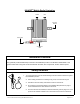
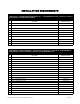


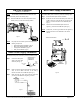
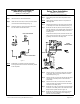
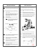
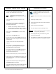
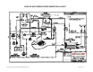
Table Of Contents
- INVADR Mobile Radio Installation Guide
- Mobile Radio Illustration
- Installation Overview
- Safety Reminder
- Installation Requirements
- Installation Instructions
- Pre-Installation Guidelines
- Mounting the INVADR Mobile Radio
- Serial Cable Connection and Routing
- EMI Filter Installation
- Radio Power Supply Installation
- MDC Power Supply Installation
- Carling Switch Installation
- Delay Timer Installation
- Antenna Installation
- VIU Connections
- INVADR Mobile Radio Testing
- Installation Checklist
- Vehicle Unit Wiring Interconnection Layout
- Mobile Antenna Distance Matrix
- Diversity Antenna Mobile Installation Detail
- Vehicle Unit Wiring Interconnection Layout - with VIU
- Vehicle Unit Wiring Interconnection Layout - Data911 w/ VIU

~\Technical Documentation\Install_Guides\MR-Guide\3-Jan-02 Page 5 of 14
40 0−512ΜΗζ ∗∆Ις ΕΡΣ ΙΤΨ ΜΟΒΙΛΕ ∆ΑΤ Α ΡΑ∆ΙΟ
TRUNK COMPARTMENT
2 sheet
metal screws
Mounting
Bracket
TX/RX1 RX2
Mounting
Bracket
TX FCC ID M17-EC8DT450TX
xxxxxx
xxxxxx
2 sheet
metal screws
Figure 2
INSTALLATION INSTRUCTIONS
Pre-Installation Guidelines
Mounting the INVADR
tm
Mobile Radio
To mount the radio, perform the following steps:
Step 1 Secure the radio into the trunk compartment. Insert four
(4) sheet metal screws in the radio brackets; two (2)
screws on either side of the radio (see Fig. 2).
CAUTION
:
If less than four (4) screws are used, the radio
can become loose in the trunk compartment.
This may cause the radio not to function
properly.
When inserting screws, be careful not to
disturb the vehicle gas tank.
Serial Cable Connection and Routing
(IPMN p/n: 156-0245-020)
1. Prior to installing new equipment, remove existing equipment
and all related components to include stock clips on radio
wiring harness and antenna.
2. Mounting of the radio, delay timer, relay, and filter will take
place in the trunk compartment (see Fig. 1) unless installing
in a vehicle without a trunk.
Figure 1
(Refer to page 10 for full schematic)
NOTE: Removal of seats, rubber mats, and other obstructions,
from inside the driver compartment, may be necessary
to facilitate routing of wires to the engine and trunk
compartments.
3. To ensure appropriate cable and wire routing, exercise the
following precautions:
Route cables away from sharp edges that can penetrate
cable insulation and damage wires.
Protect wires with silicone rubber grommets when
routing through the engine compartment firewall or
through other holes with sharp edges.
Use high-quality electrical tape when covering exposed
wires in the engine compartment.
Avoid routing cables through areas exposed to extreme
heat, such as the exhaust system.
Keep wires routed through the engine compartment
away from hot and/or moving parts.
4. Prior to drilling holes in the engine compartment firewall,
inspect both sides to avoid obstructions.
5. For grounding point, use the engine block or the negative (-)
terminal of the vehicle battery. Ground connection surfaces
must be free of paint, rust, and other corrosion to maximize
performance and avoid damage.
6. To simplify troubleshooting problems, label all connecting
points and wires.
The serial cable connects the radio to the Mobile Data Computer
(MDC) located in the driver compartment.
To connect the serial cable, perform the following steps:
Step 1 Attach the 20-foot serial cable male
connector
(DB9M – see Fig. 3)
to the
radio.
Step 2 Route the female connector
(DB9F – see Fig. 4)
to the
driver compartment and connect to the serial port located
on the rear of the MDC.
NOTE
: Route the serial cable to minimize foot pressure and
other potential stresses. Use split loom tubing and nylon
cable ties for cable protection.
(If connecting a Voice Interface Unit, see page 8 for instructions).
Figure 3
Figure 4