
User Manual
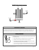
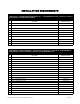
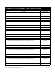

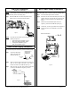
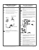
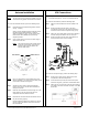
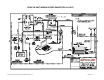
Table Of Contents
- INVADR Mobile Radio Installation Guide
- Mobile Radio Illustration
- Installation Overview
- Safety Reminder
- Installation Requirements
- Installation Instructions
- Pre-Installation Guidelines
- Mounting the INVADR Mobile Radio
- Serial Cable Connection and Routing
- EMI Filter Installation
- Radio Power Supply Installation
- MDC Power Supply Installation
- Carling Switch Installation
- Delay Timer Installation
- Antenna Installation
- VIU Connections
- INVADR Mobile Radio Testing
- Installation Checklist
- Vehicle Unit Wiring Interconnection Layout
- Mobile Antenna Distance Matrix
- Diversity Antenna Mobile Installation Detail
- Vehicle Unit Wiring Interconnection Layout - with VIU
- Vehicle Unit Wiring Interconnection Layout - Data911 w/ VIU

~\Technical Documentation\Install_Guides\MR-Guide\3-Jan-02 Page 6 of 14
DRIVER
COMPARTMENT
TRUNK COMPARTMENT
400−512ΜΗζ ∗∆ΙςΕΡΣΙΤΨ ΜΟΒΙΛΕ ∆ΑΤΑ ΡΑ∆ΙΟ
EMI Filter Installation
(IPMN p/n: 127-0020-001)
MDC Power Supply Installation
NOTE
: The EMI Filter protects the radio and filters out noise.
To install the filter, perform the following steps:
Step 1 Secure the EMI Filter in the trunk compartment of the
vehicle (see Fig. 5) near radio mounting location.
Figure 5
NOTE: For proper wire connections, perform the steps for the
following components:
Radio Power Supply Installation, page 6
MDC Power Supply Installation, page 6
Carling Switch Installation, page 7
Delay Time Installation, page 7
Radio Power Supply Installation
To install the radio power connection, perform the following steps:
Step 1 Connect the radio power
cable to the power cable
extension (see Fig. 6).
Step 2 Route and wire the power cable extension red wire
(#12
AWG)
, via the 15 AMP in-line fuse, to the radio (+)
terminal connection on the EMI Filter (see Fig. 7).
Step 3 Route and wire the power cable extension black wire
(#12 AWG)
to the EMI Filter’s negative (-) terminal.
Figure 7
To install the MDC power connection, perform the following steps:
Step 1 Connect the MDC power cable to the MDC.
Step 2 Route and wire the red and clear MDC power wires via a
3 AMP in-line fuse, routing the red wire
(#12 AWG)
to the
battery (+) terminal connection on the EMI Filter (see
Fig. 8).
Step 3 Route and wire the black MDC power wire to the
negative (-) terminal on the EMI Filter (see Fig. 8).
NOTE
: A black wire
(#12 AWG)
is grounded from the negative (-)
terminal connection on the EMI Filter to the vehicle
chassis.
Figure 8
radio’s power
cable
power
cable
extension
Figure 6