
User Manual
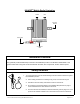
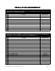
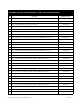

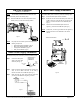
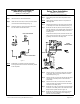
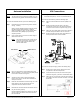
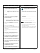
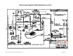
Table Of Contents
- INVADR Mobile Radio Installation Guide
- Mobile Radio Illustration
- Installation Overview
- Safety Reminder
- Installation Requirements
- Installation Instructions
- Pre-Installation Guidelines
- Mounting the INVADR Mobile Radio
- Serial Cable Connection and Routing
- EMI Filter Installation
- Radio Power Supply Installation
- MDC Power Supply Installation
- Carling Switch Installation
- Delay Timer Installation
- Antenna Installation
- VIU Connections
- INVADR Mobile Radio Testing
- Installation Checklist
- Vehicle Unit Wiring Interconnection Layout
- Mobile Antenna Distance Matrix
- Diversity Antenna Mobile Installation Detail
- Vehicle Unit Wiring Interconnection Layout - with VIU
- Vehicle Unit Wiring Interconnection Layout - Data911 w/ VIU

~\Technical Documentation\Install_Guides\MR-Guide\3-Jan-02 Page 8 of 14
400−512ΜΗζ ∗∆ΙςΕΡΣΙΤΨ ΜΟΒΙΛΕ ∆ΑΤΑ ΡΑ∆ΙΟ
Antenna Installation
VIU Connections
NOTE
: Two (2) antennas are mounted and installed on the roof
of the vehicle using specific measurements for distance.
To mount and install the antennas, perform the following steps:
Step 1 Install antennas (see sample drawing DT450-10-0201
and Fig. 11 below).
Observe correct separation between antennas (refer to
the Mobile Antenna Distance Matrix for midpoint
distance calculations on page 11) and minimum Near
Field Exclusion Zone (NFEZ) for proper diversity
reception operation.
Step 2 Cut a mounting hole in the roof of the vehicle using an
electric drill or hole saw.
NOTE
: The antenna-mounting hole provides ground
connection to the antenna. Ensure that a
metal-to-metal connection between the
antenna shields exists.
Figure 11
NOTE
: Figure 11 represents the recommended front-to-rear
antenna installation. The receiver antenna (RX2) should
be the antenna nearest to the light bar.
Step 3 All antenna mounts must be environmentally tight.
Install or use O-rings to seal the antenna base to the
rooftop of the vehicle.
Step 4 Route the coaxial cables to the radio through one of the
hollow spaces in the roof supports into the trunk
compartment where the radio is mounted.
NOTE
: Both antennas should be checked and tested to ensure
they are functioning properly.
If these installation guidelines are followed, it is safe for
persons to stand at a distance no less than 39 inches
from the antennas.
If connecting a VIU, an additional serial cable is required.
10-ft serial cable (
IPMN p/n: 156-0245-010)
included with VIU
To connect the serial cables, perform the following steps:
Step 1 Attach 20-ft serial cable male connector
(DB9M)
to the
radio.
Step 2 Route the female connector
(DB9F)
to the driver
compartment and connect to the serial port located on
the rear of the VIU near the microphone hang up clip.
Step 3 Attach the 10-foot serial cable male connector
(DB9M)
to
the other serial port located on the rear of the VIU.
Step 4 Route the female connector
(DB9F)
serial cable to the
serial port located on the rear of the MDC.
Figure 12
To connect the VIU power supply, perform the following steps:
Step 1 Route the VIU’s power supply cable from the driver
compartment to the trunk compartment.
Step 2 Connect the black
(#18 AWG)
wire from the VIU power
cable to the negative (-) terminal on the EMI Noise Filter.
Step 3 Attach the red
(#18 AWG)
wire of the VIU power cable via
the 3 AMP in-line fuse to the radio connection on the EMI
Noise Filter.
Figure 13
RX2 Antenna
TX/RX1 Antenna
NFEZ