IPSeries M64450G25 High Speed Mobile Radio Product Owner’s Manual Date Released: March 20, 2006 Document #: 516.80539.POM Revision: A Copyright 2005 IPMobileNet, Inc.
The term “IC”: before the radio certification number only signifies that Industry of Canada technical specifications were met. Operation is subject to the following two (2) conditions: (1) this devise may not cause interference, and (2) this device must accept any interference, including interference that may cause undesired operation of this device. The following U.S. Patents apply to this product: U.S.
TABLE OF CONTENTS SECTION 1: OVERVIEW..........................................................................................................................3 Product Description....................................................................................................................3 SECTION 2: SETUP AND CONFIGURATION METHODS .....................................................................5 High Speed Mobile Radio Setup and Configuration Method..............................................
SECTION 1: OVERVIEW Product Description The M64450G25 Mobile Radio works within a frequency range of 450-506 MHz and requires a 1/4-wavelength antenna. The IPSeries High Speed Mobile Radios are intelligent devices designed for the challenging requirements of mobile data applications. Mounted in vehicles, other intelligent devices may connect to the serial or Ethernet ports for connectivity back to the Internet Protocol Network Controller (IPNC) and other such servers.
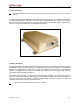
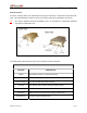
SECTION 1: OVERVIEW External Features As seen in the figure below, the mobile radio technology is enclosed in a compact and sturdy aluminum case. The external features consist of a series of connectors and ports as described in this section. a The product warranty becomes immediately void if an uncertified or unauthorized individual removes the mobile radio cover.
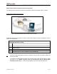
SECTION 2: SETUP AND CONFIGURATION METHOD Mobile Radio-to-Mobile Computer Setup and Configuration The following section describes the setup and configuration method for the mobile radio in a vehicle.
SECTION 3: INSTALLATION INSTRUCTIONS Installation Overview This chapter provides the basic steps involved in the installation process of an IPSeries High Speed Mobile Radio into a vehicle. This chapter includes wire routing and connections between the mobile radio, other components, and the vehicle’s power. a To prevent personal injury and vehicle damage, exercise extreme caution throughout the installation process and follow the reminders listed below.
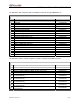
SECTION 3: INSTALLATION INSTRUCTIONS The table below lists components that are available for purchase through IPMobileNet, Inc.
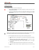
SECTION 3: INSTALLATION INSTRUCTIONS Installation Instructions Pre-Installation Guidelines Prior to installing new equipment, perform the following steps: a 1. Remove existing equipment and all related components to include stock clips on radio wiring harness and antenna. 2. As shown in the figure below, mounting of the mobile radio, delay timer, relay, and EMI filter (noise filter) will take place in the trunk compartment, unless installing in a vehicle without a trunk.
SECTION 3: INSTALLATION INSTRUCTIONS 4. Prior to drilling holes in the engine compartment firewall, inspect both sides to avoid obstructions. 5. For grounding point, use the engine block or the negative (-) terminal of the vehicle battery. Ground connection surfaces must be free of paint, rust, and other corrosion to maximize performance and avoid damage. Do not tie to the vehicle chassis. 6. To simplify troubleshooting problems, label all connecting points and wires.
SECTION 3: INSTALLATION INSTRUCTIONS Serial Cable Connection and Routing The serial cable connects the mobile radio to the mobile computer located in the driver compartment. To connect the serial cable, perform the following steps: Step 1 Attach the 20-foot serial cable male connector (DB9M) to the mobile radio. Step 2 Figure 6 Route the female connector (DB9F) to the driver compartment and connect to the serial port located on the rear of the mobile computer.
SECTION 3: INSTALLATION INSTRUCTIONS Figure 8: Delay Timer Installation Step 4 Route a red wire (#12 AWG) from the ignition connection on the Delay Timer to the ignition switch in the driver compartment (see the figure above). The ignition wire should be fused with 2A fuse. Step 5 Route a red wire (#12 AWG) from the first and last output connections on the Delay Timer to the Automotive Power Relay.
SECTION 3: INSTALLATION INSTRUCTIONS Switch Installation (DPST Heavy Duty Toggle) To install the switch, perform the following steps: Step 1 Mount the switch in the selected location. Step 2 Route and wire a red wire (#12 AWG) from the switch to the Automotive Power Relay (see the figure below). Step 3 Ground the switch by routing and wiring a black wire from the switch to the chassis ground. Figure 9: Carling Switch Installation M64450G25-FCCRpt.
SECTION 3: INSTALLATION INSTRUCTIONS Mobile Radio Power Supply Installation To install the mobile radio power connection, perform the following steps: Step 1 Route and connect the power cable to the EMI filter, as shown in the figure below. Figure 10: Power Supply Installation Step 2 a Route and connect the other end of the power cable to the rear of the mobile radio to the power connector (13.8 VDC) connection.
SECTION 3: INSTALLATION INSTRUCTIONS Antenna Configuration Two (2) antennae are mounted and installed on the roof of the vehicle using specific measurements for distance. To mount and install the antennae, perform the following steps: Step 1 Install antennae (see the figure below). 1 2 Observe correct separation between antennae (refer to Table 7: Mobile Antenna Distance Matrix).
SECTION 3: INSTALLATION INSTRUCTIONS The previous figure represents the recommended front-to-rear antenna installation. The receiver antenna (RX2) should be the antenna nearest to the light bar. Step 3 All antenna mounts must be environmentally tight. Install or use O-rings to seal the antenna base to the rooftop of the vehicle. Step 4 Route the coaxial cables to the mobile radio through one of the hollow spaces in the roof supports into the trunk compartment where the mobile radio is mounted.
SECTION 3: INSTALLATION INSTRUCTIONS Measuring Insertion Loss To measure Insertion Loss of an unterminated length of coax, perform the following steps: Step 1 Connect the antenna to be tested to the appropriate Antenna Analyst. Step 2 Turn on the Antenna Analyst and the Return Loss is displayed in dB to the left of the VSWR curve. To switch from the RETL mode to VSWR mode, refer back to the previous set of instructions. Step 3 Divide the result by two (2).
SECTION 3: INSTALLATION INSTRUCTIONS Mobile Installation Layout Diagrams Figure 12 Vehicle Unit Wiring Interconnection Layout Table 7 lists the mobile radio antenna distances by frequency band. TABLE 7: MOBILE ANTENNA DISTANCE MATRIX Frequency Band in MHz Center Frequency in MHz Antenna Spacing for ¼ Wave Ant (inches) Wavelength (inches) Near-Field Exclusion Zone* (inches) ¼ Wave Length (inches) 130-140 135 65.4 87.3 10.9 21.8 140-150 145 61.2 81.4 10.2 20.4 150-160 155 57.0 76.2 9.
SECTION 3: INSTALLATION INSTRUCTIONS Figure 13 Diversity Antenna Mobile Installation Detail (Typical Installation) M64450G25-FCCRpt.
SECTION 3: INSTALLATION INSTRUCTIONS Preliminary Testing and Troubleshooting This section provides a functional preliminary test for the mobile radio once installed. It is used to determine the condition of new mobile radios before being placed into service. Checklist of Required Material The table below provides a checklist of the tools and equipment required to perform the preliminary test procedure. TABLE 8: CHECKLIST OF REQUIRED MATERIAL TO PERFORM PRELIMINARY TESTING NO.
SECTION 3: INSTALLATION INSTRUCTIONS Base Station Setup for Testing The system must be programmed with the customer’s parameters before any tests are made on the mobile radio. To prepare the base station to be used in the mobile radio test, perform the following steps: Step 1 On the laptop at the Windows desktop, click on the Start button and select Accessories, Communications, and HyperTerminal. Step 2 Power up the base station.
SECTION 3: INSTALLATION INSTRUCTIONS Preliminary Test Procedure and Troubleshooting Prior to performing this procedure, the IPNC IP address must be known. Note taking during preliminary testing is crucial to ensure necessary information is gathered to use for additional testing or if the mobile radio needs to be submitted for repair. To test mobile radio functionality, perform the following steps: Step 1 Perform a visual inspection of the mobile radio and its connections.
SECTION 3: INSTALLATION INSTRUCTIONS # If a message window appears indicating the connection was unsuccessful, perform the following troubleshooting steps: 1. Ensure the serial and power cables are properly connected. 2. Verify that the mobile radio lock LED (light emitting diode) is on, indicating the mobile radio has power. 3. Ensure that the SLIP2IPMN dial-up connection is running. 4. If problem persists after retrying, replace the serial cable with one that is known to be working properly.
SECTION 3: INSTALLATION INSTRUCTIONS Step 8 At the desktop, click on the Start button and select Programs and MS-DOS Prompt. The MS-DOS window displays. Step 9 Ping the IPNC commanding the transmitter to send 25 messages of 500 characters each to the IPNC as well as a response through Receiver 1 back to the laptop or desktop PC by typing in the following command at the MS-DOS prompt replacing NNN.NNN.NNN.NNN with the IPNC IP address: Ping NNN.NNN.NNN.
SECTION 3: INSTALLATION INSTRUCTIONS Confirming High Speed Mobile Radio Receiver Sensitivity This set of instructions provides the user with a list of required equipment and steps needed to confirm mobile radio Receiver sensitivity. Requirements IPSeries High Speed Mobile Radio DC power supply, 13.
SECTION 4: FACTORY TEST PROCEDURE Equipment List The following table lists the equipment required to perform the M64450G25 Mobile Radio Factory Test Procedure: TABLE 9: EQUIPMENT REQUIRED TO PEREFORM FACTORY TEST PROCEDURE QTY DESCRIPTION MANUFACTURER MODEL 2 PC’s One for Mobile One for Base 1 Service Monitor – Communication Test Set 1 Digital multimeter 1 DC power supply w/ ammeter, 13.
SECTION 4: FACTORY TEST PROCEDURE Programming and Configuring Mobile Radio Once the appropriate equipment for performing the factory test are gathered, perform the following steps to program and configure an M64450G25 Mobile Radio: Step 1 Enter the mobile radio serial number, date test being performed, and tester’s name on the Test Data Sheet (see Appendix B). Step 2 Program the radio to the current Firmware revision using the AVR programming utility.
SECTION 4: FACTORY TEST PROCEDURE Test Connections Test Equipment Setup The test equipment should be configured as shown in the figure below: Mobile Radio Connections Perform the following steps to connect the mobile radio properly: Step 1 Connect the GPS antenna. Step 2 Connect a serial cable and launch IPMessage. Step 3 Connect a load to the transmitter antenna port. Step 4 Connect the power cable to a voltage source of 13.8 VDC able to deliver 25 amps of continuous current.
SECTION 4: FACTORY TEST PROCEDURE Receiver Alignments and Tests TCXO Operation Perform the following steps to check the operation of the TCXO: Step 1 In IPMessage, type “status = pps, cal” in the command field and press [ENTER]. Step 2 Read the reported error values for the TCXOs. Step 3 Continue using the “status = pps, cal” command, until GPS is acquired. Step 4 Repeat the command observing the error values. Step 5 Observe that the TCXO “error ppb” continues to adjust until it settles at +/-200.
SECTION 4: FACTORY TEST PROCEDURE Step 3 Adjust Receiver 1 filters. - Step 4 Connect an RF cable from the “Duplex Out” port to Receiver 1 Probe U64 pin 1 with the High Frequency Probe Adjust CV12, CV5, and CV8 for the correct waveform as shown in the figure below Adjust Receiver 2 filters.
SECTION 4: FACTORY TEST PROCEDURE Amplitude: Varies Atten Hold: Off Output Port: RF Out AFGen1 Freq: 1.000 kHz AFGen to: FM 5 KHz AFGen2 Freq: 1.000 kHz AFGen2 to: Off Ext Load R: 600 ohm Filter 1: 300 Hz HPF Filter 2: 3 kHz LPF Step 2 Test Receiver 1, as follows: Step 3 Connect an RF cable from the Service Monitor’s “RF Out” port to the antenna port of Receiver 1 At the Service Monitor, reduce the “Amplitude” until the SINAD meter indicates 12 dB SINAD The amplitude must be -115 dBm or less.
SECTION 4: FACTORY TEST PROCEDURE Step 3 Adjust Receiver 2, as follows: - Connect an RF cable from the Service Monitor’s “RF Out” port to the antenna port of Receiver 2 Observe the Service Monitor while adjusting CV1 for minimum distortion – Distortion must read 3.
SECTION 4: FACTORY TEST PROCEDURE Audio AC and DC Voltages and Balances Perform the following steps to adjust the Receiver Audio AC and DC voltages and balance: Step 1 Set the Service Monitor, as follows: - Select the "RX" function - Set "RF Gen Freq" to the receive frequency of the mobile radio under test - Set the Service Monitor to display DC volts and AC Volts - Connect an oscilloscope 1x probe from TP1 on the base station control board to the “audio in” connector on the Service Monitor - Set
SECTION 4: FACTORY TEST PROCEDURE Receiver Calibration Each receiver must be calibrated at four (4) points to ensure the proper operation of Intelligent Diversity Reception and to provide the IPNC with correct information about the signal strength of received mobile data.
SECTION 4: FACTORY TEST PROCEDURE Step 8 Step 9 Calibrate Receiver 2, as follows: - Connect an RF cable from the Service Monitor's RF Out port to the antenna port of Receiver 2 - In IPMessage, type the command “receiver = 2” and observe that Receiver 2 is selected - Set the Service Monitor to measure 12db SINAD - Reduce signal amplitude on the Service Monitor until 12dB SINAD is reached - Record the value - In IPMessage, type the command “12DB SINAD = “ and the recorded value - Set the Servic
SECTION 4: FACTORY TEST PROCEDURE Transmitter Alignment Tests Transmitter Output Step 1 Set the Service Monitor to measure the transmitter frequency of the base station. Step 2 Set the Service Monitor filters to “<20 Hz HPF” and “15 kHz HPF”. Ensure the Service Monitor can handle the full power transmission of the base station otherwise attach an attenuator to the output of the base station transmitter antenna port before transmitting into the Service Monitor.
SECTION 4: FACTORY TEST PROCEDURE Transmitter Power Step 1 Set the Service Monitor to measure the transmitter frequency of the base station. Step 2 Set the Service Monitor filters to “<20 Hz HPF” and “15 kHz HPF”. Ensure the Service Monitor can handle the full power transmission of the base station otherwise attach an attenuator to the output of the base station transmitter antenna port before transmitting into the Service Monitor.
SECTION 4: FACTORY TEST PROCEDURE Step 11 After completion of Data Quality and MSR tuning, record Firmware Settings. File the Tune and Align Data Sheet with the Firmware setting in the IPMN Network. Hardware Timing Troubleshooting For trouble shooting data quality and MSR failures hardware timing can be verified as follows. The figure below is an oscilloscope plot of a down-link data message from the base station to the mobile.
SECTION 4: FACTORY TEST PROCEDURE The mobile radio’s microcontroller, upon detecting a step response in the RSSI (caused by the base station's transmitter coming up to power), waits a period of time equal to the programmed value of the mobile's carrier detect delay time. The microcontroller then instructs the modem to search for the modem synchronization preamble. When the base station instructs the modem to look for sync tones the modem's CS line transitions low. This can be seen in the above plot.
SECTION 4: FACTORY TEST PROCEDURE The next plot is the same as before but now the scope is in the peak detect acquisition mode. After the mobile radio detects a step response in the RSSI (caused by a down-link transmission), the mobile radio's microcontroller waits an amount of time equal to the programmed value of the "carrier detect delay time" then instructs the modem to look for frame sync. When the microcontroller instructs the modem to look for frame sync, it asserts the modem's CS line (active low).
SECTION 4: FACTORY TEST PROCEDURE Message Success Rate Testing and Burn-In After completion of the alignment and testing, the base station shall undergo Burn In and Final Testing. Install the mobile radio in the MSR screen room as shown in the figure below. Sequence Tests Step 1 In IPMessage, verify latest version of the mobile radio firmware by entering the ‘version’ command. Step 2 Verify the serial number and MAC I.D. – match the label on the unit by typing ‘serial number’ and ‘radio mac address’.
SECTION 4: FACTORY TEST PROCEDURE Final Inspection The final inspection of the mobile radio is a critical step that translates directly into confidence in the product. Several areas must be checked on every base station before it can be shipped: Screws- every screw hole must have the proper screw tightened the proper amount. The screws must be new and cannot have rounded shoulders. Screw heads must be flush to the case.
SECTION 5: FCC LABEL M64450G25 Data Transceiver FCC Label Placement M64450G25 Data Transceiver FCC Label M64450G25-FCCRpt.
APPENDIX A: CIRCUIT BOARD DIAGRAMS M64450G25 IPSeries High Speed Mobile Radio Circuit Board M64450G25-FCCRpt.
APPENDIX B: M64450G25 TEST DATA SHEET Date: Serial Number: Firmware Revision: End User: Tester: Adjustment / Alignment Procedures TCXO Frequency Error Parameter TCXO freq error ppb Specification Using GPS as freq ref Cal Value ≤1 PPM Receiver Injection Parameter Injection Frequency Error at RX Antenna Port Specification Measured +400 Hz Set 45MHz Filter Waveform Parameter Initial Waveform set Receiver SINAD Parameter 12dB SINAD at TP1 Specification Receiver 1 Measured Receiver 2 Measured Rec
APPENDIX B: M64450G25 TEST DATA SHEET Receiver Calibration Parameter Specification Receiver 2 Measured Specification Measured -95 +2 dBm "Noise" value reported with -95dBm signal injected "Noise" value reported with -105dBm signal injected Receiver 1 Measured -105 + 2 dBm Transmitter Output Parameter Transmitter Frequency Error (Frequency controlled by software; record measured value) + 400 Hz 4.8 kHz +75 Hz Transmitter Modulation (Deviation) 40 watts Output Power at 13.