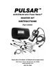
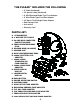
PULSAR ™ with Electronic Fuse Saver® MASTER KIT INSTRUCTIONS Part #9001 Innovative Products of America Incorporated® 234 Tinker Street, Woodstock, NY 12498 www.ipatools.
IMPORTANT SAFETY INSTRUCTIONS t This manual contains safety and operating instructions for the PULSAR™. Refer to this manual for information on safe operation. t Read, understand and follow all safety messages and instructions printed in this manual and on the equipment before operating. t “DANGER” indicates an imminently hazardous situation which, if not avoided, results in death or serious injury to the operator or bystanders.
t Do not place tester directly above or below battery. t Make sure tester cable clamps make tight connections. t Battery explosion can cause injury. ACID BURNS: t t t t Battery acid is highly corrosive sulfuric acid. Wear safety goggles (user and bystander.) Wear safety gloves. Make sure someone can hear you or is close enough to provide aid when working near battery. t Have plenty of fresh water and soap nearby.
The USER is responsible for using the PULSAR™ in accordance with manufacturer’s specifications and recommendations. This tool could be damaged or could damage the circuits (such as vehicle computers, modules and other sensitive equipment) when used improperly or on the wrong circuit. WARNING: The PULSAR™ may be used to power up circuits which may control moving devices. i.e. fan motors, starts etc. Be sure to keep hands and feet, tools and equipment away from any moving parts at all times.
THE PULSAR™ INCLUDES THE FOLLOWING: x x x x x x x x 3’ Cable (hardwired) 10’ ground cable (hardwired) 6” Mini/Standard Blade Type Fuse Adapter 6” Maxi Blade Type Fuse Box Adapter 10’ Bench Test/Voltage Probe Adapter Soft Storage Case Instructions Warranty Card PARTS LIST: A. STRAIN RELIEF B. 3’ MASTER TEST CABLE C. 50 AMP MAXI COMPUTER PROTECTION FUSE D. FEMALE WEATHERPROOF PLUG E. GROUND WIRE (18 GAUGE) F. GROUND CLIP G. MALE WEATHERPROOF ENDS H. #9000-5 BATTERY CLIP ADAPTER I.
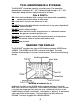
STANDARD EQUIPMENT EXPLAINED 3’ HARD WIRED CABLE (TWO RED 10 AWG WIRES) (Fig.1 – B ) is to be connected directly in-line with the provided adapters. This cable features a 50-amp maxi fuse for protection. When the tool is used properly, this Maxi fuse should never blow. The maxi fuse protects the components should the PULSAR™ accidentally be connected across the battery terminals (positive and negative). DO NOT BYPASS THE MAXI FUSE OR PLACE A LARGER FUSE INTO THE HOLDER OR THE WARRANTY WILL BE VOIDED.
TOOL MAINTENANCE & STORAGE The PULSAR™ should be stored in a cool dry area. The operating temperature is between 32° - 95° Fahrenheit and storage is 0° – 125° Fahrenheit. Keep moisture away from tool at all times. DOs & DON’Ts DO clean tool and display with a scratch free damp cloth (completely squeeze out excess water or mild soap). DO store tool in its soft case when not in use. DO NOT leave on the dash board in the hot sun or any area subjected to excessive heat. DO NOT store in direct sunlight.
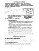
GETTING STARTED NOTE: The battery clips are different colors. When hooked in reverse, the PULSAR™ displays a “-” (negative) line next to the amperage reading. This indicates the flow of current only and does not affect the operation of the tool. 1. SET-UP: a. Connect the 10’ ground cable to a clean engine or battery ground connection. NOTE: This ground is for Pulsars’™ onboard computer only, it does not carry the main testing load. b.
Automatic Mode allows the technician to diagnose circuits “hands free” while maintaining full circuit protection. Manual Mode allows the technician to use the push button for momentary amperage pulsing in Bench Testing, Probing Circuits, or momentarily turning circuits on. a. To Select Automatic Mode: depress the three-way rocker switch to the right. Power is applied to the circuit immediately after the Amp Limit is set and engaged. b. To Select Manual Mode: depress the three-way rocker switch to the left.
6. USING PULSAR™ IN AUTOMATIC MODE: Once the amperage limit has been selected, press and hold the control knob down for 1 second and then release. (A “.”displays on the LOWER DISPLAY indicating that the amperage setting is locked.) Once the control knob is released, the PULSAR™ immediately sends current into the circuit (up to the limit setting). If a short circuit or overload is detected, the PULSAR™ immediately cuts power (See Sec. 11 on “Pulsing”).
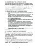
10. SETTING PEAK HOLD: Peak Hold can only be displayed in Automatic Mode. To engage Peak Hold, press and release the Manual Push Button. Once Peak Hold is engaged, the letter “P” is displayed in the Upper Display to the left of the Current Reading. Peak hold records EXAMPLE OF UPPER DISPLAY the highest current read by the ™ IN PEAK HOLD MODE (Fig. 6) Pulsar . To exit peak hold and resume monitoring amperage real time, press and release the Manual button.
. INRUSH CURRENT MODE: This mode may be used for testing equipment that requires a significant Inrush Current under normal operation. Example: Blower motor draws 10amp under constant load, but requires an initial inrush of 25 amps when first powered up. Inrush Current Mode on the PULSAR™ extends the PULSAR’s™ default trip time from 150 Milliseconds to 350 milliseconds allowing equipment with heavy Inrush requirements to operate normally while powered by the PULSAR™. a.
PARASITIC DRAW SET UP Check the vehicle for any excessive loads prior to installing the Memory Saver. Examples: Dome lights, head lights, cooling fans, radios etc. With overall power drain minimized, install your Memory Saver. If you do not have a Memory Saver, you can use an external battery and jumper leads to temporarily bypass the vehicles battery until the PULSAR™ setup is complete. a. Connect the PULSAR™ to the Battery Clip Adapter. b. Connect the PULSAR™ ground cable to the battery or chassis ground.
NOTE: Latching is a common term used to describe a vehicle’s computer system turning on and staying on for extended periods of time when a car is at rest. Latching can lead to parasitic draw and drained batteries. m. When testing is complete, follow reverse instructions from section “i” back to prevent memory loss to the vehicle’s computer system. Be sure to reapply memory savers and other protective devices. n.
a. Choose the supplied Battery Clip Adapter or the #9031 Bench Test/Voltage Probe Adapter. b. Connect in line with the PULSAR™ and connect to the circuit. c. Select Manual Mode (See Section 7) d. Select the desired amperage limit for the equipment to be tested. e. Send power while viewing the current draw. This allows you to inspect and test your equipment while preventing damage and avoiding guesswork.
PULSAR™ One Year Limited Warranty Innovative Products of America Incorporated® has established a Limited One Year Warranty Policy for the PULSAR™ with Electronic Fuse Saver® not including any wearable parts i.e. batteries, etc. YR- 1 Year Limited Warranty/Return or Replace Policy: These products are covered for 1 year from date of original user purchase under the stipulations of the Standard Warranty.