Mobile Universal Trailer Tester #9008-SE SUPER MUTT® DELUXE OPERATOR’S MANUAL © 2012 Innovative Products of America®, Incorporated. All rights reserved. This material may not be reproduced, displayed, modified or distributed without the express prior written permission of the copyright holder. For permission, contact info@ipatools.com. Innovative Products of America® Incorporated 888-786-7899 | www.ipatools.
LETTER FROM THE PRESIDENT OF IPA My name is Peter Vinci and I am the president of IPA®. I would like to first thank you for your interest in IPA®’s product line and share my commitment to you, our products and our policies. In today’s world, we have all experienced the lack of service and consideration demonstrated by many companies after you buy their products. They say whatever they can to make the sale, and then it’s like pulling teeth to get any service response out of them.
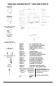
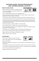
9008-SE SUPER MUTT® DELUXE PARTS RED AIR HOSE #7900AP-18AS BLUE AIR HOSE #7900AP-23AS FEMALE 2 PRONG PLUG POWER ADAPTER #7900K-93 Faceshield Hanger Qty. 1 - #7900K-34 CONTROL FOB #7900K-34B CONTROL FOB BATTERY (12V Alkaline Energizer AE or A23) 5 FT. CABLE 7 ROUND PIN #7900K-1 10 FT.
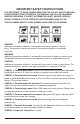
IMPORTANT SAFETY INSTRUCTIONS IT IS IMPORTANT TO READ, UNDERSTAND AND FOLLOW ALL SAFETY MESSAGES AND INSTRUCTIONS PRINTED IN THIS MANUAL AND ON THE EQUIPMENT BEFORE OPERATING. IF SAFETY INFORMATION IS NOT HEEDED, SERIOUS INJURY OR DEATH TO THE OPERATOR OR BYSTANDERS MAY OCCUR. THE FOLLOWING SAFETY ALERT SYMBOLS ARE USED IN THIS MANUAL. DANGER: Indicates a hazardous situation, if not avoided, will result in death or serious injury.
BATTERY GASES, TESTER PREPARATION AND TESTER/CHARGER LOCATION RISK OF EXPLOSION • Gases produced by a battery are highly explosive. • Wear safety goggles and protective clothing, both users and bystanders. • Use in an area having at least four air changes per hour. • Read, understand and follow all instructions for charger, battery, vehicle and any equipment used near battery and charger. • Do not smoke, strike a match, place metal tools on battery or cause a spark in the vicinity of the battery.
GENERAL CHARGER USE RISK OF ELECTRIC SHOCK AND FIRE • Before connecting power cord to charger, make sure controls are set to off. • DC power only. • Do not plug directly into AC wall outlet. • Do not remove or bypass the grounding pin. • Do not operate charger with damaged cord or plug. Replace cord or plug immediately.
QUICK SET-UP GUIDE NOTE: The Super MUTT ® Deluxe is an advanced diagnostic tool designed to eliminate guesswork and make your job easier. As a general rule, if something is wrong with your trailer’s electrical system, the MUTT ® will beep and blink LEDs to indicate the problem. Air brake testing is straightforward, but should be operated only AFTER reading the instruction manual. Both Lights and Air Brakes can be operated by remote control. 1. CHOCK ALL WHEELS BEFORE TESTING BRAKES. 2.
QUICK REFERENCE GUIDE OPERATION AND TESTING ELECTRICAL TESTING 1. CABLE TESTING: It is always recommended to use the cable tester to verify that the MUTT®’s 7 round pin cable is in proper working order before trailer testing. To perform the Cable Test, insert both ends of the 7 pin cable one in each receptacle on the MUTT®’s side. Once the cable is installed, turn the MUTT® On to verify the continuity between both ends of the cable.
4. TO FIND STICKY OR BAD BRAKE SERVOS: To check the mechanical servo operation, slowly turn the PSI up and note the point at which both servos engage. Then reduce PSI and note the point at which the servos release. They should engage and release together at the same time. To check for a leaking servo, you can charge Service Side and close ball valve on the Emergency Side. There should be no increase in PSI on the Emergency Side.
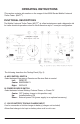
OPERATING INSTRUCTIONS This section contains information on the usage of the #9008 Series Mobile Universal Trailer Tester. (MUTT®) FUNCTIONAL DESCRIPTIONS The Mobile Universal Trailer Tester (MUTT®) is a fleet maintenance and a diagnostic aid for trailer electrical operations wired to North American style 7 round pin configuration. The following describes the Testing Panel (Fig. 3). A. AIR CONTROL SWITCH Select between Emergency, Remote and Service Side air control.
D. ANTENNA Receives RF signal from wireless remote up to 100 feet. Binding post allows antenna length insertion for further distances in inclement weather. It is recommended that the antenna be installed for optimum performance. E. BACKLIT 30 AMP AMMETER Meter shows current draw of a selected circuit up to 30 AMPS. F. 30 AMP FUSE SOCKET Overload protection. G. MUTE SWITCH Flip switch up to mute alert sounds. H.
ELECTRICAL/LIGHT TESTING PROCEDURES 7 ROUND PIN TRAILER TESTER MANUAL MODE To avoid false readings, visually inspect trailer socket for corroded and/or squeezed pins. Bad or broken socket pins can cause false readings. (Replace socket if pins are broken or socket appears to be out of tolerance. Clean all connections and load socket with dielectric grease). 1. Prior to any MUTT® testing, connect the 7 pin connector or you will receive erroneous readings.
10. After the Ground Integrity Test, the Control Knob (Fig. 3-L) may be rotated in either direction to select a circuit to diagnose. The corresponding Circuit Indicator (Fig. 3-M) illuminates indicating the selected circuit. AUTO CYCLE MODE NOTE: Cannot be accessed when auxiliary or brake circuit is selected. 1. After Ground Integrity has been established, momentarily push and release the Control Knob (Fig. 3-L). The Auto Cycle Indicator (Fig. 3-I) illuminates. 2.
The diagnostic chart (Pg. 15) references some of the ABS codes and the method for releasing them from the CPU utilizing the SUPER MUTT®’s Auxiliary circuit. BLINK CODE DIAGNOSTICS The Meritor WABCO Enhanced Easy-Stop Trailer ABS ECU detects any electrical fault in the trailer ABS. Each of the faults has a code. When a fault occurs, the ECU stores the code for that fault in the memory. There are two kinds of faults: active and stored.
Blink Code Problem Area Action 3 Sensor BUI Determine sensor location. Check senor installation. Make necessary repairs. 4 Sensor YEI Determine sensor location. Check senor installation. Make necessary repairs. 5 Sensor BU2 Determine sensor location. Check senor installation. Make necessary repairs. 6 Sensor YE2 Determine sensor location. Check senor installation. Make necessary repairs. 7 External ABS Modulator Valve Verify proper electrical modulator installation. Check power supply.
REMOTE FUNCTIONS REMOTE PROGRAMMING With MUTT® in the OFF position, hold down the large button (Fig. 4-1) on the remote while simultaneously turning the MUTT® power On. Release after 2 seconds. The remote is now programmed. Up to 24 separate remotes may be programmed to a single MUTT®. HOW TO USE THE WIRELESS REMOTE 1. LIGHTS & ELECTRIC BRAKES Press button to select the next available electrical circuit (including electric brakes when available). 2.
ANTENNA INSTALLATION See Fig. 5 for installation of the Antenna (included in the accessories bag) WARNING INDICATORS Explanation of the diagnostic functions of the warning indicators.
POWER TO TESTER WARNING INDICATORS VOLTAGE INDICATOR • When the battery supply voltage drops to 9V or less, the MUTT® shuts down power to all circuits and the voltage indicator flashes red. Charging or replacing the battery is required to continue testing. • Between 10V-11V, the indicator is RED, showing the battery is too low. • Between 11V-12V, the indicator is YELLOW, showing the battery is low. REVERSED POLARITY INDICATOR • Flashes when battery clamps have been crossed at the battery posts.
AUTO SHUTDOWN FEATURE To preserve battery life, the MUTT® enters a Sleep mode if inactive after 20 minutes with the power On. • A sound is emitted every 10-20 seconds to inform the operator of the condition. • Activation of any test mode takes the MUTT® out of Sleep mode. CABLE TESTING The MUTT® has a special cable feature to test 7 round pin cables for continuity. The cable testing feature can be used to test a tractor’s cable or the supplied MUTT® cable.
OPERATING INSTRUCTIONS FOR AIR BRAKE CONTROLS DANGER WARNING!! BEFORE CONNECTING AIR TO TESTER PANEL, BE SURE TO CHOCK ALL WHEELS ON TRAILER TO PREVENT TRAILER FROM ROLLING. TRAILER CAN ROLL AND CAUSE SERIOUS INJURY OR DEATH. DO NOT CONNECT SHOP AIR UNTIL COMPLETING THE PRE-TEST PROCEDURES STEPS 1 THROUGH 7 (PAGE 21). FAILURE TO FULLY UNDERSTAND THESE WARNINGS CAN RESULT IN MINOR TO SERIOUS INJURY AND POSSIBLY DEATH. AIR PANEL (Fig. 7) A. B. C. D. E. F. G.
AIR BRAKE PRE-TEST PROCEDURE 1. Read and understand all Safety Warnings before operation. 2. CHOCK ALL WHEELS BEFORE TESTING OR ATTACHING SHOP AIR TO UNIT. 3. Push the main Power Source rocker switch (Fig. 3-B) to the middle Off position. 4. Move Air Control rocker switch (Fig. 3-A) to the middle Emergency setting. 5. Turn both Emergency Side and Service Side ball valves (Fig. 7-C & E) to the Closed position. 6.
SERVICE SIDE – MANUAL LEAK DOWN TEST 1. Press Air Control rocker Switch to the right Service position (located on upper panel). Turn power switch to desired the power source. 2. Turn the Service Side (blue) ball valve (Fig. 7-E) to the Open position. 3. Once the Service Side (Fig. 7-F) gauge reflects the desired pressure, then turn the ball valve to the Closed position to begin leak down test. 4. Note any PSI drop after stabilization of pressure. 5.
ADDITIONAL TESTING PROCEDURES There are many safety and operational functions to test on a trailer, but there are a few which are widely viewed as VERY important. With this tester, these tests can be performed without the truck or tractor, quickly, accurately, and in most cases, with only one person. Below are a few common system checks that can be performed using the MUTT®. • Leak Down Testing on both Service Side and Emergency Side. • One man leak and shake testing throughout the trailer.
AXLE AND WHEEL INSTALLATION • Insert axle (Fig. 8-A) into left and right axle bores Fig. 8-B) at rear underside of the MUTT®. • Slide 1 spacer (Fig. 8-C) onto each side of the axle (Fig. 8-A). • Install 1 wheel (Fig. 8-D) onto each side of the axle (Fig. 8-A) with valve stem facing away from the MUTT®. • Insert 1 E-Clip (Fig. 8/9-E) into the groove (Fig. 9-F) in the axle end in front of the wheel to each side. • Check tire pressure. It must not exceed 8PSI. Fig. 8 - Axle and Wheel Installation Fig.
REMOVING THE HEAD In the event your Deluxe Super MUTT® should need service or repair, the Super MUTT® has been designed so that the “Head” which contains all the electro-mechanical components can be easily removed to simplify and reduce the cost of the packing and shipping process. You will need only a phillips head screwdriver to remove the 8 screws that attach the head to the cart body. See the illustrations below.
TYPICAL TRAILER WIRING Note: Not all trailers/vehicles are wired to this standard. The use of an electrical circuit is necessary to ensure proper match of vehicle’s wiring to trailer’s wiring. On the 6 way plugs, the 12V wire and electric brake wire may be reversed on some trailers (particularly horse trailers).
OPTIONAL ACCESSORIES & RELATED PRODUCTS #9008-UPKIT (This kit updates the #9008-SE to the #9008-DL). Comes with... • 2 extra remotes • 3 Amp charger • Face shield • Rain cover • Shoulder screws #9008-DL: Includes 3 remotes, 10 ft. chassis ground cable, 7-way cable, 6 ft. glad hands, face shield, battery charger, rain cover.
Limited Three Year Warranty MOBILE UNIVERSAL TRAILER TESTER #9008-SE SUPER MUTT® DELUXE Innovative Products of America® Incorporated has established a Limited Three Year Warranty Policy for the Mobile Universal Trailer Tester 9008 Series, not including any wearable parts, i.e. tires, clips, batteries, etc. Three Year Limited Warranty/Return or Replace Policy: The product is covered for three years from the date of original user purchase under the stipulations of the Standard Warranty.