
User's Manual


IPICO Spider User Manual V1.0 draft 20071123 RWD .doc 12/12/2007 Page 8
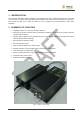
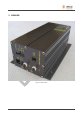
3.1.1 Transmitter unit
This unit manages the TX loops to provide energy to tags.
Figure 4: Transmitter unit
Battery level indicator:
Three indicators show Low (L), Medium (M) and High (H) voltage levels. As the power supply is
managed by the Power Supply unit, the light should always show H or M.
Transmitter unit powered indicator:
This indicator should be lit when the reader is switched on to show that the transmitter unit is
powered.
Manual tuning button:
This button is used to start a manual tuning of the antennas. When the reader is switched on, the
reader will automatically tune the loops. The result of this tuning will be displayed on the TX tuning levels
indicators. This manual tuning must not be done when tags are detected. If so, tags can be missed. The aim
of the manual tuning is to tune the antennas if something changed in the antennas environment (metallic
part…). In most of the cases, the automatic tuning done when the reader is switched on is sufficient.
TXA Tuning Level indicator:
When the indicator is lit, the tuning is correct. When it is flashing and a beep is sounding, something
is not correct. Turn the power off, check that your antennas are installed correctly and restart the system.
TXB Tuning Level indicator:
When the indicator is lit, the tuning is correct. When it is flashing and a beep is sounding, something
is not correct. Turn the power off, check that your antennas are installed correctly and restart the system.
USB port for
transmitter setup
Manual tuning
button
Battery level
indicator
TXA tuning
level indicator
TXB tuning
level indicator
Transmitter unit
powered indicator
CPU activity indicator
Antennas power
off button