IPitomy IP400 User Guide i
Table of Contents CHAPTER 1 INTRODUCTION ............................................................................................1 VoIP Gateway Features ...................................................................................................1 Package Contents ..............................................................................................................2 Physical Details ............................................................................................................
P/N: 956YD30001 Copyright 2007. All Rights Reserved. Document Version: 1.0 All trademarks and trade names are the properties of their respective owners.
Chapter 1 Introduction 1 This Chapter provides an overview of the VoIP Gateway features and capabilities. Congratulations on the purchase of your new VoIP Gateway. The VoIP Gateway bridges traditional Public Switched Telephony Network (PSTN) and IP network. It digitizes and compresses analog voice signal on Public Switched Telephone Network (PSTN), and transmits it to the Internet Protocol (IP) network.
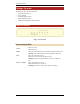
IP Phone User Guide Package Contents The following items should be included: • The VoIP Gateway Unit • Power Adapter • One RJ45 Ethernet cable. • Quick installation guide • CD-ROM containing the on-line manual. Physical Details Figure 1: Front Panel Front-mounted LEDs Power Status LAN Line 1, 2, 3 and 4 On - Power On. Off - No Power. On - The VoIP Gateway has successfully registered to SIP server. Flashing - The VoIP Gateway has not registered to SIP server. On – The LAN port is active.
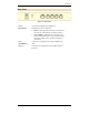
Introduction Rear Panel Figure 2: Rear Panel Power Connect the supplied power adapter here. Reset Button This button has two (2) functions: • Reboot. When pressed for less than 6 seconds and released, the VoIP Gateway will reboot (restart). • Clear All Data. When press for 6 seconds longer then released. ALL data are cleared and restored to the factory default values, and the VoIP Gateway will reboot. LAN (10/100BaseT) Connect to a broadband router using a standard LAN cable.
Chapter 2 Installation 2 This Chapter covers the physical installation of the VoIP Gateway. Requirements • • TCP/IP protocol must be installed on all PCs. For Internet Access & VoIP, you must have access to Internet. Procedure 1. Choose an Installation Site Select a suitable place on the network to install the VoIP Gateway. Ensure the VoIP Gateway is powered OFF. 2.
Chapter 3 Configuration and Application Examples 3 This Chapter provides some examples of VoIP Gateway configuration and application. Configuration The VoIP Gateway can be configured to register to a SIP server and make calls through the server. In SIP server environment, the SIP server handles the registration and serves as a proxy server for call signal. The VoIP Gateway may be configured to work in Direct Inward Dial (DID) mode or regular mode.
Configuration and Application Examples Application Example 2- PSTN Trunk for IP PBX Organization with IP PBX can use the VoIP Gateway as PSTN trunk for connecting its IP PBX to PSTN. You can configure the IP PBX as VoIP Gateway’s SIP server and setup the dial plan on the IP PBX, the VoIP Gateway can be used as PSTN trunk to the IP PBX.
Chapter 4 Setup This Chapter provides Setup details of the VoIP Gateway 4 Overview This chapter describes the setup procedure for configuring the VoIP Gateway from a web browser. After changing the settings, the new settings won’t take effect until you save and reset the VoIP Gateway. Use the Reset button on the Reset screen. Configuration Program The VoIP Gateway contains an HTTP server. This enables you to connect and configure it by using your Web Browser. Your web browser must support JavaScript.
Setup If you can't connect If the VoIP Gateway does not respond, check the following: • The VoIP Gateway is properly installed, LAN connection is OK, and it is powered ON. You can test the connection by using the "Ping" command: • Open the MS-DOS window or command prompt window. • Enter the command: ping 192.168.0.250 If no response is received, either the connection is not working, or your PC's IP address is not compatible with the VoIP Gateway's IP Address. (See next item.
IP400 User Guide Main Menu The main menu, on the left, contains links to the most-commonly used screen. From the menu, check the following screens, and configure as necessary for your environment. Details of these screens and settings are described in the following sections of this chapter.
Setup Basic Setup Screen After logging in, you will see the Basic Setup screen. This screen allows you to setup the network configuration. Figure 4: Basic Setup Screen Data - Basic Setup Screen Network Setup Dynamic IP address If selected, the VoIP Gateway will obtain its IP address and related information from a DHCP Server. Select this option only if your LAN has a DHCP Server. Fixed IP address If selected, you must assign the following data to the VoIP Gateway.
IP400 User Guide SIP Service Screen This screen lets you configure the SIP servers and the related parameters. Figure 5: SIP Service Screen Data - SIP Service Screen SIP Server SIP Proxy Address Enter the address of the SIP Proxy Server. SIP Proxy Port Enter the port used for connections to the Server above. Registration Time This sets the "Idle Timeout" for the SIP Proxy Server Login. An Idle connection will be terminated after this time period. Enter the desired value.
Setup Signaling Signaling Port The UDP port that the VoIP Gateway uses for incoming call setup request. RTP RTP Port Enter the Base UDP port which the VoIP Gateway uses for RTP and RTCP. The VoIP Gateway uses a block of UDP ports for sending/receiving RTP and RTCP packets from this port number. IP Tos/DiffServ Call Signaling Packets TOS field in IP header for outgoing SIP packets.
IP400 User Guide Line Settings Screen The VoIP Gateway deals with the calls from FXO ports in two ways, Direct Inward Dial (DID) mode and non-DID mode. In DID mode, when there is an incoming call from FXO ports, the VoIP Gateway forwards the call directly to the SIP proxy server. In non-DID mode, when an incoming call from FXO port is detected, the VoIP Gateway then presents a dial tone and waits for the caller to dial the destination number before setting up the call.
Setup Voice Screen This screen is for selecting and configuring the voice codec, voice parameters, and the FXO line settings. Figure 7: Voice Screen Data - Voice Screen Preferred Coders Preferred Coders Select the desired codec. Voice Coders Packatization The duration that the VoIP Gateway samples voice signal and compresses it into a packet before sending to remote SIP device. VAD Set the Voice Activity Detection ON or OFF for the voice codec.
IP400 User Guide Answer after Number of rings the VoIP Gateway waits before answering incoming calls. Dial out wait Enter the desired time the VoIP Gateway waits after seizing a telephony port and before dialing out DTMF digits Dial out battery threshold Before seizing a FXO port for dialing out, the VoIP Gateway detects voltage level of the port to ensure that the port is connected and available. If the voltage level is below this threshold level, the port is declared unavailable.
Setup Ring frequency Max The maximum ring frequency for the FXO port to detect. Ring Validation Time Select the time for the FXO port to detect a valid ring. Ring Indication Delay Select the desired value from the list. Ring Timeout Select the desired option for the ring timeout. Ring Threshold The minimum voltage level which the incoming ringing signal must present for the VoIP Gateway to detect it. Ringer Impedance Choose the desired value to satisfy the maximum ringer impedance specification.
IP400 User Guide Management Screen This page allows you to change the user password for the VoIP Gateway. Figure 8: Management Screen Data - Management Screen Management Gateway Username Enter the login name. Gateway Password Enter the new password Re-enter to Confirm Re-enter the new password here.
Setup Factory Default Screen This screen allows you to set the VoIP Gateway back to its factory default configuration. Any existing settings will be deleted. Factory Default Restore factory defaults Click this button will reset the VoIP Gateway to its factory default settings. WARNING ! This will delete ALL of the existing settings.
IP400 User Guide Firmware Upgrade Screen The firmware (software) in the VoIP Gateway can be upgraded using your web browser. You may use this screen to upgrade your VoIP Gateway's firmware. Figure 9: Firmware Upgrade Screen To perform the Firmware Upgrade: 1. 2. 3. Click the Browse button and navigate to the location of the upgrade file. Select the upgrade file. Its name will appear in the File Path field. Click the Upgrade button to commence the firmware upgrade.
Setup Reboot Screen This page allows you to restart (reboot) the VoIP Gateway. Figure 10: Reboot Screen Data - Reboot Screen Button Restart System Click this button to restart the VoIP Gateway. All connections to or through the VoIP Gateway will be lost.
IP400 User Guide Gateway Screen This screen displays the status of the VoIP Gateway. Figure 11: Gateway Screen Data - Gateway Screen Gateway Information Firmware Version The version of the current firmware installed. MAC Address This shows the MAC Address for the VoIP Gateway Current Time It displays the current date and time of the system. Internet Connection IP Address The IP Address of the VoIP Gateway. IP Subnet Mask The Subnet Mask for the IP Address above.
Setup VoIP Screen This screen displays the phone numbers and the status of the SIP registration. Figure 12: VoIP Status Screen Data - VoIP Status Screen Line Status Telephone Number The telephone number associated with this line. Registration Status This shows the status of the connection to the SIP Server.
IP400 User Guide Set Log Level Screen The Logs record various types of activity on the VoIP Gateway. Use the Set Log Level screen to configure this feature. Figure 13: Set Log Level Screen Data - Set Log Level Screen Event Types Telephony Telephony events will be logged SIP Events related to SIP server are logged. DSP Events related to the DSP will be logged. Dial Plan Dial Plan events are logged Others Other operations (not covered by the selections above) will be logged.
Setup Event Logs Screen This screen displays the event logs of the VoIP Gateway. Figure 14: Event Logs Screen Data - Event Logs Screen Event Logs Event Logs Current log data is displayed in this panel. Refresh Screen Click this button to update the messages shown on screen. Clear Log Delete all data currently in the Log. This will make it easier to read new messages.
Appendix A Troubleshooting A This Appendix covers the most likely problems and their solutions. Overview This chapter covers some common problems that may be encountered while using the VoIP Gateway and some possible solutions to them. If you follow the suggested steps and the VoIP Gateway still does not function properly, contact your dealer for further advice. General Problems Problem 1: Can't connect to the VoIP Gateway to configure it.
Troubleshooting address of the VoIP Gateway, do the following steps: 1. Insert the supplied CD-ROM into your drive. Run ScanIP.exe in the root folder. A pop-up window will be shown on the PC. 2. 3. Click the SCAN button. The utility will detect the presence of the VoIP Gateway and if the VoIP Gateway is detected, it will display the MAC address, IP address, subnet mask and other information in the table. 4. Click the Exit button to close the utility.
Appendix B Specifications B VoIP Gateway Model IP400 Dimensions 176mm(W) * 115mm(D) * 36mm(H) Operating Temperature 0° C to 40° C Storage Temperature -10° C to 70° C VoIP Signaling Protocol Session Initiation Protocol (SIP) Voice Codecs G.711, G.729AB, G.