
Product Manual


25FP-250-00
1
07/2012
Specifications Information and Repair Parts Manual 25FP Series
x
Please read and save this Repair Parts Manual. Read this manual and the General Operating Instructions carefully before attempting to assemble,
install, operate or maintain the product described. Protect yourself and others by observing all safety information. The Safety Instructions are contained
in the General Operating Instructions. Failure to comply with the safety instructions accompanying this product could result in personal injury and/or
property damage! Retain instructions for future reference. AMT reserves the right to discontinue any model or change specifications at any time without
incurring any obligation.
©2012 American Machine & Tool Co., Inc. of PA, A Subsidiary of The Gorman-Rupp Company, All Rights Reserved.
Periodic maintenance and inspection is required on all pumps to insure proper operation. Unit must be clear of debris and sediment. Inspect for leaks and loose bolts. Failure
to do so voids warranty.
25FP Fire Pump Series
Refer to pump manual 1808-633-00 for General Operating and Safety Instructions.
DESCRIPTION
This is a single-stage centrifugal pump designed for agriculture or firefighting service. It is close coupled to an internal combustion engine air cooled
engine and protected by a roll frame equipped with four carry handles. The pump is compact and light weight designed for portability. Pump construction
is rugged and allows for easy maintenance.
Units are designed to handle clean water or water containing small (1/16” maximum spherical diameter) solids. Suction and discharge ports are 2-1/2”
NPT threaded. Discharge includes a built in bronze check valve to allow use of an exhaust or hand operated priming system.
Liquid temperature range is 40°F to 180° (4°C to 82°C). Maximum casing pressure is 180 psi (1240 kPa). For use with nonflammable liquids that are
chemically compatible with pump component materials.
SPECIFICATIONS
Suction inlet…………………………………………….2-1/2” NPT Female
Discharge outlet……………………………………….2-1/2” NPT Female
Dimensions overall (Length x Width x Height)
25FP13AR & 25FP13HR..…………………………….….(32” x 32” x 25”)
25FP23AR………………………………………….………(41” x 32” x 25”)
Engine and fuel tank size
25FP13AR……………………………..…..B&S Vanguard 13hp, 8 quarts
25FP13HR……………………………….…...…Honda GX390, 6.9 quarts
25FP23AR............................................B&S Vanguard 23hp, 10 gallons
BASIC CONSTRUCTION
Pump is constructed of cast aluminum. Engine shaft is sealed with a
self-lubricating mechanical seal that consists of a silicon carbide
stationary ring, carbon rotating head, stainless steel spring and Viton®
elastomer. Discharge flange gasket and casing O-ring are Viton®.
UNPACKING
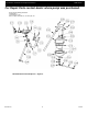
Refer to repair parts illustration and parts list to aid in identifying parts.
Unpack and separate all pump components from shipping/packaging
materials, making sure all parts are accounted for. Retain all manuals
for future reference.
Package should contain:
Pump/engine completely assembled and mounted in roll
frame.
Rubber feet with fasteners bag.
Frame handle parts bag.
Frame panel and parts bag.
Engine owner’s manual
Pump general safety manual,
Specifications information and repair parts manual.
ASSEMBLY
Roll Frame Handle Assembly:
1. Install pivot bearing (A6) in frame hole. Ends of bearing must
be flush with outside of frame rail.
2. Hold handle (A3) perpendicular to frame tube.
3. Slide handle end ears over frame tube until handle tube end
contacts frame.
4. Align handle ear hole with bearing in frame.
5. Install pivot pin (A5) and pin end cotter (A7).
6. Install lock pin (A4) in other handle ear hole. Secure with
cotter (A7).
7. Handle can be locked in the up or down position with lock
pin.
8. Repeat procedure for [3] three remaining handles.
Roll Frame Panel Assembly:
1. Slide panel mounting brackets (A10) over frame tube where
panel will be positioned.
2. Align slots in end of panel (A9) with holes in mounting
brackets.
3. Fasten panel to brackets with bolts (A11) and nuts (A12)
provided.
Rubber Feet Assembly:
1. Install bolt (20) through rubber foot (A19) center hole.
2. Slide bolt through hole provided in lower tube of roll frame.
3. Fix in position with nut (21).
4. Repeat for [3] three remaining feet.
Battery Tray Assembly:
1. Locate battery tray (A14) on frame rail.
2. Install mounting bolts (A15) with washers (A16), and nuts
(A17).
3. Install “J” bolts in tray slots.
4. Install hold down angle on “J” bolt threaded ends, fix with
wing nuts.
Fuel Tank Frame Assembly: [25FP23AR]
1. Position fuel tank frame (A32) on roll frame.
2. Align holes in tank frame ears with holes in roll frame tubes
and cross member.
3. Install mounting bolts (A33 & A34) and nuts (A35) securing
tank frame to roll frame.
4. Install fuel line from bottom of tank to fuel pump on engine
with hose clamp provided.
5. Install purge line from top of tank to engine purge line with
connector and hose clamp.