Wireless MJPEG Network Camera Advanced Installation Guide Version 1.
P REFACE Thank you for purchasing the Wireless MJPEG Network Camera, a powerful and high-quality image wireless network camera. The camera can be installed as a standalone system within your application environment easily and quickly, and supports remote management function so that you can access and control it using a Web browser on your PC.
Contents Preface......................................................................................................... 1 Chapter 1 Introduction To Your Camera................................................ 3 1.1 Checking the Package Contents ............................................... 3 1.2 Getting to Know Your Camera................................................... 4 1.3 Features and Benefits................................................................. 6 1.4 System Requirement................
C HAPTER 1 I NTRODUCTION TO Y OUR C AMERA 1.1 Checking the Package Contents Check the items contained in the package carefully. You should have the following: 5 5 5 5 5 5 5 One Wireless MJPEG Network Camera. One AC Power Adapter. One External Antenna. One Camera Stand. One Ethernet Cable (RJ-45 type). One Installation CD-ROM. One Quick Installation Guide. NOTE Once any item contained is damaged or missing, contact the authorized dealer of your locale.
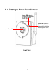
1.2 Getting to Know Your Camera Power LED indicates the camera is powered on with the steady amber light. Link LED indicates the camera’s network connectivity with the flashing green light.
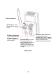
External Antenna Screw Hole is used to connect the camera stand. DC Power Connector is used to connect the AC power adapter, in order to supply power to the camera. Reset Button will restart the camera when it is pressed quickly; when it is long pressed for five seconds, the camera will resume the factory default settings. Rear View -5- Ethernet Cable Connector is used to connect the network cable, which supports the NWay protocol so that the camera can detect the network speed automatically.
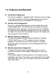
1.3 Features and Benefits Surveillance Supported The camera supports “nightshot mode” to deliver clearer images in the dark environment. Enable motion detection and setup automated email alerts and upload FTP for security. Remote Control Supported By using a standard Web browser or the bundled Ultra View software application, the administrator can easily change the configuration of the camera via Intranet or Internet. In addition, the camera can be upgraded remotely when a new firmware is available.
1.4 System Requirement Networking LAN: 10Base-T Ethernet or 100Base-TX Fast Ethernet. WLAN: IEEE 802.11b/g. Accessing the Camera using Web Browser Platform: Microsoft® Windows® 2000/XP/Vista Macintosh OSX CPU: Intel Pentium III 350MHz or above RAM: 128MB Resolution: 800x600 or above User Interface: Microsoft® Internet Explorer 5.0 or above Apple Safari 2 or above Mozilla Firefox 2.00 or above Accessing the Camera using Ultra View Platform: Microsoft® Windows® 2000/XP/Vista.
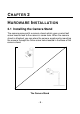
C HAPTER 2 H ARDWARE I NSTALLATION 2.1 Installing the Camera Stand The camera comes with a camera stand, which uses a swivel ball screw head to lock to the camera’s screw hole. When the camera stand is attached, you can place the camera anywhere by mounting the camera through the three screw holes located in the base of the camera stand.
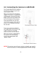
2.2 Connecting the Camera to LAN/WLAN Use the provided Ethernet cable to connect the camera to your local area network (LAN). When you connect the AC power adapter, the camera is powered on automatically. You can verify the power status from the Power LED on the front panel of the camera. Once connected, the Link LED starts flashing green light and the camera is on standby and ready for use now.
2.3 Applications of the Camera The camera can be applied in multiple applications, including: Monitor local and remote places and objects via Internet or Intranet. Capture still images and video clips remotely. Upload images or send email messages with the still images attached. The following diagram explains one of the typical applications for your camera and provides a basic example for installing the camera.
C HAPTER 3 A CCESSING THE C AMERA 3.1 Using IP Finder The camera comes with a conveniently utility, IP Finder, which is included in the Installation CD-ROM, allowing you to search the camera on your network easily. 1. Insert the Installation CD-ROM into your computer’s CD-ROM drive to initiate the Auto-Run program. 2. Click the IP Finder item to launch the utility. The control panel will appear as below.
3.2 Accessing to the Camera Whenever you want to access the camera: 1. Open the Web browser on your computer (for example, Microsoft Internet Explorer in this guide) 2. Type the default IP address (192.168.0.30) or the IP address found by IP Finder in the Address bar, and then press [Enter]. 3. When the login window appears, enter the default User name (admin) and password (admin) and press OK to access to the main screen of the camera’s Web Configuration. Enter the IP address of the camera here.
After you login into the Web Configuration of the camera, the main page will appear as below: Zoom In Buttons Nightmode Button Live View/Setup Switch Function Buttons Camera Information Live View Image The main page of the Web Configuration provides you with many useful information and functions, including: Camera Information – Display the camera’s location and the current date & time. The information can be modified in the Web Configuration.
Function Buttons – Use these buttons to control the video functions. z Manual Record allows you to record and save a video clip. z Snapshot allows you to capture and save a still image. z Browse allows assign the destination folder to store the video clips and still images. Zoom In Buttons – Click the buttons to zoom in the live view image by 1x, 2x, and 3x. Nightmode Button – Click the button to enable the “nightshot mode” to deliver clearer images in the dark environment.
3.3 Configuring the IP Address of the PC If you are failed to access to the camera, please check the IP address of your computer. When you connect the camera to your computer directly to proceed with configuration of the camera, you need to set up the IP addresses to be in the same segment for the two devices to communicate. 1. On your computer, click Start > Control Panel to open the Control Panel window. 2. Double-click Network Connection to open the Network Connection window. 3.
C HAPTER 4 C ONFIGURING THE C AMERA 4.1 Using the Web Configuration You can access and manage the camera through the Web browser and the provided software application Ultra View. This chapter describes the Web Configuration, and guides you through the configuration of the camera by using the web browser. To configure the camera, click Setup on the main page of Web Configuration. The Web Configuration will start from the Basic page.
4.2 Using Smart Wizard The camera’s Smart Wizard lets you configure your camera easily and quickly. The wizard will guide you through the necessary settings with detailed instructions on each step. To start the wizard, click Smart Wizard in the left menu bar. Step 1. Camera Settings Enter the name for the camera and place. Enter the administrator password. Step 2. IP Settings Select the IP setting according to your network: DHCP, Static IP, or PPPoE.
Step 3. Email Settings Enter the required information to be able to send email with image. Step 4. Wireless Networking Select Enable to enable the wireless function of the camera, and then complete the required settings.
Step 5. Confirm Settings This step shows the configuration of your camera. When you confirm the settings, click Apply to finish the wizard and reboot the camera. Otherwise, click Prev to go back to the previous step(s) and change the settings; or click Cancel to end the wizard and discard the changes.
4.3 Basic Setup The Basic menu contains three sub-menus that provide the system settings for the camera, such as the Camera Name, Location, Date & Time, and User management. Basic >> System Basic - Camera Name: Enter a descriptive name for the camera. - Location: Enter a descriptive name for the location used by the camera. Indication LED This item allows you to set the LED illumination as desired. There are two options: Normal and OFF.
Basic >> User Administrator To prevent unauthorized access to the camera’s Web Configuration, you are strongly recommend to change the default administrator password. Type the administrator password twice to set and confirm the password. General User - User Name: Enter the user’s name you want to add to use the camera. - Password: Enter the password for the new user. When you are finished, click Add/Modify to add the new user to the camera.
4.4 Network Settings The Network menu contains three sub-menus that provide the network settings for the camera, such as the IP Setting, DDNS Setting, IP Filter, and Wireless network.
Network >> Network IP Setting This item allows you to select the IP address mode and set up the related configuration. - DHCP: Select this option when your network uses the DHCP server. When the camera starts up, it will be assigned an IP address from the DHCP server automatically. - Static IP: Select this option to assign the IP address for the camera directly. You can use IP Finder to obtain the related setting values. IP Enter the IP address of the camera. The default setting is 192.168.0.30.
DDNS Setting With the Dynamic DNS feature, you can assign a fixed host and domain name to a dynamic Internet IP address. Select the Enable option to enable this feature. Then, select the Provider from the pull-down list and enter the required information in the Host Name, User Name, and Password boxes. Please note that you have to sign up for DDNS service with the service provider first.
Network >> IP Filter The IP Filter setting allows the administrator of the camera to limit the users within a certain range of IP addresses to access the camera. Start/End IP Address Assign a range of IP addresses that are not allowed to access the camera by entering the Start IP address and End IP address. When you are finished, click Add to save the range setting. You can repeat the action to assign multiple ranges for the camera. For example, when you enter 192.168.0.50 in Start IP Address and 192.
Click Site Survey to display the available wireless networks, so that you can easily connect to one of the listed wireless networks. List of searching results - Wireless Mode: Select the type of wireless communication for the camera: Infrastructure or Ad-Hoc. - Channel: Select the appropriate channel from the list. - Authentication: Select the authentication method to secure the camera from being used by unauthorized user: Open, Shared-key, WPA-PSK, and WPA2-PSK.
If you select Open or Shared-key as the Authentication mode, you need to complete the following settings: Encryption: Select the WEP option to enable the data encryption feature to secure the camera within the wireless network. Format: Once you enable the Encryption feature, you need to determine the encryption format by selecting ASCII or HEX. ASCII format causes each character you type to be interpreted as an eight-bit value.
4.5 Setting up Video The Video menu contains two sub-menus that provide the video settings for the camera.
Video >> Camera Image Setting - Brightness: Adjust the brightness level from 0 ~ 100. - Contrast: Adjust the contrast level from 0 ~ 100. - Saturation: Adjust the colors level from 0 ~ 100. Click Default to restore the default settings of the three options above. - Mirror: Select the Horizontal option to mirror the image horizontally. Select the Vertical option to mirror the image vertically. - Light Frequency: Select the proper frequency according to the camera’s location: 50Hz, 60Hz, or Outdoor.
4.6 Event Server Configuration The Event Server menu contains two sub-menus that allow you to upload images to FTP, and send emails that include still images. When you complete the required settings for FTP, or Email, click Test to test the related configuration is correct or not. Once the camera connects to the server successfully, click Apply.
Event Server Setting>> FTP FTP - Host Address: Enter the IP address of the target FTP server. - Port Number: Enter the port number used for the FTP server. - User Name: Enter the user name to login into the FTP server. - Password: Enter the password to login into the FTP server. - Directory Path: Enter the destination folder for uploading the images. For example, /Test/. - Passive Mode: Select the Enable option to enable passive mode.
4.7 Motion Detect The Motion Detect menu contains the command and option that allow you to enable and set up the motion detection feature of the camera. The camera provides two detecting areas. To enable the detecting area, select Window 1 or 2 from the pulldown list, and then select Enable. When the detecting area is enabled, you can use the mouse to move the detecting area and change the area coverage. - Name: Assign a name to the detecting area.
4.8 Event Config The Event Config menu contains four sub-menus that provide the commands to configure event profiles. Event Configuration >> General Setting - Snapshot/Recording Subfolder: You can assign a given subfolder for captured file. Otherwise, leave this option blank to use the default setting.
Event Configuration >> Arrange Schedule Profile This sub-menu displays the scheduled profile(s). To customize the profile, click Add and then enter a descriptive name for the profile in the prompt dialog window. After entering the profile name, click OK and the profile is added to the Schedule Profiles list. To delete the profile, select the profile in the list and click Delete. - Profile Name: Display the profile name that you select in the Schedule Profiles list.
Event Configuration >> Motion Detect Trigger Select the Enable option to enable the trigger function of the camera, so that you can send captured images within the detecting area to the FTP server, or email receiver. You have to configure corresponding settings, such as FTP server and email server, to enable this feature. - Schedule Profile: Select a schedule profile from the pull-down list. - Action: Select the destination that the captured images will be sent to: Send Email, or FTP Upload.
4.9 Tools The Tools menu provides the commands that allow you to restart or reset the camera. You can also backup and restore your configuration, and upgrade the firmware for the camera.
Factory Reset Click Reset to restore all factory default settings for the camera. System Reboot Click Reboot to restart the camera just like turning the device off and on. The camera configuration will be retained after rebooting. Configuration You can save your camera configuration as a backup file on your computer. Whenever you want to resume the original settings, you can restore them by retrieving the backup file.
4.10 Information The Information menu displays the current configuration and events log of the camera. Device Info Display the Basic, Video, Network, and Wireless settings of the camera. System Log The Logs table displays the events log recorded by the system.
C HAPTER 5 A PPENDIX A.1 Specification Image Sensor Sensor Resolution 1/4” color CMOS 640x480 Video Compression Video resolution MJPEG VGA/QVGA/QQVGA; 30fps max. System Hardware Processor RAM ROM Power ARM9 base 16MB SDRAM 4MB NOR Flash DC 5V Communication LAN WLAN 10/100Mbps Fast Ethernet, auto-sensed, Auto-MDIX IEEE 802.
User Interface LAN Antenna Reset LEDs Software OS Support Browser Software Windows 2000/XP/Vista Internet Explorer 5.0 or above Apple Safari 2 or above Mozilla Firefox 2.
A.2 Glossary of Terms NUMBERS 10BASE-T 100BASE-TX 10BASE-T is Ethernet over UTP Category III, IV, or V unshielded twisted-pair media. The two-pair twisted-media implementation of 100BASET is called 100BASE-TX. A ADPCM AMR Applet ASCII ARP AVI Adaptive Differential Pulse Code Modulation, a new technology improved from PCM, which encodes analog sounds to digital form.
C Communication Connection Communication has four components: sender, receiver, message, and medium. In networks, devices and application tasks and processes communicate messages to each other over media. They represent the sender and receivers. The data they send is the message. The cabling or transmission method they use is the medium. In networking, two devices establish a connection to communicate with each other.
E Enterprise network Ethernet An enterprise network consists of collections of networks connected to each other over a geographically dispersed area. The enterprise network serves the needs of a widely distributed company and operates the company’s mission-critical applications. The most popular LAN communication technology. There are a variety of types of Ethernet, including 10Mbps (traditional Ethernet), 100Mbps (Fast Ethernet), and 1,000Mbps (Gigabit Ethernet).
H HEX Short for hexadecimal refers to the base-16 number system, which consists of 16 unique symbols: the numbers 0 to 9 and the letters A to F. For example, the decimal number 15 is represented as F in the hexadecimal numbering system. The hexadecimal system is useful because it can represent every byte (8 bits) as two consecutive hexadecimal digits. It is easier for humans to read hexadecimal numbers than binary numbers.
ISP ISP (Internet Service Provider) is a company that maintains a network that is linked to the Internet by way of a dedicated communication line. An ISP offers the use of its dedicated communication lines to companies or individuals who can’t afford the high monthly cost for a direct connection. J JAVA Java is a programming language that is specially designed for writing programs that can be safely downloaded to your computer through the Internet without the fear of viruses.
Network NWay Protocol network appear to the Internet as a single address. For routing messages properly within your network, each device requires a unique IP address. But the addresses may not be valid outside your network. NAT solves the problem. When devices within your network request information from the Internet, the requests are forwarded to the Internet under the router's IP address. NAT distributes the responses to the proper IP addresses within your network.
Protocol Communication on the network is governed by sets of rules called protocols. Protocols provide the guidelines devices use to communicate with each other, and thus they have different functions. Some protocols are responsible for formatting and presenting and presenting data that will be transferred from file server memory to the file server’s net work adapter Others are responsible for filtering information between networks and forwarding data to its destination.
S Server SIP SMTP SNMP Station Subnet mask It is a simple computer that provides resources, such as files or other information. SIP (Session Initiated Protocol) is a standard protocol that delivers the real-time communication for Voice over IP (VoIP), which establishes sessions for features such as audio and video conferencing. The Simple Mail Transfer Protocol is used for Internet mail. Simple Network Management Protocol. SNMP was designed to provide a common foundation for managing network devices.
U UDP User Name Utility UTP The User Datagram Protocol is a connectionless protocol that resides above IP in the TCP/IP suite The USERNAME is the unique name assigned to each person who has access to the LAN. It is a program that performs a specific task. Unshielded twisted-pair. UTP is a form of cable used by all access methods. It consists of several pairs of wires enclosed in an unshielded sheath. W WAN WEP Windows WPA WPA2 Wide-Area Network.