Instruction Manual VD-8810 Wireless Video Door Intercom ATTENTION: Thank you for purchasing the VD-8810 wireless video door intercom. Before permanently mounting the camera door unit on the wall, please confirm successful wireless signal transmission by testing the quality of the voice and video image. Before installation and use, please read this instruction manual thoroughly and keep it safe for future reference.
Miscellaneous Using the system Introduction and installation Index 2 Introduction Index........................................................................................ 02 What’s included in your kit............................................ 03 Safety precautions............................................................ 04 Operation guidelines......................................................... 04 Identifying the key system components Camera Door unit....................................
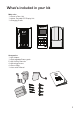
What’s included in your kit Main units 1 x Camera Door Unit 1 x Indoor Portable LCD Display Unit 1 x Charging Cradle Accessories 1 x AC Adaptor 1 x Rechargeable Battery pack 6 x AA Alkaline Batteries 4 x Mounting Screws 4 x Screw Pegs 1 x Instruction Manual 3
Safety precautions Please observe the following precautions when installing or using the kit. Rechargeable Battery Pack Do not disassemble the battery pack. Do not dispose of in fire. Use only the specified battery pack in the kit. Do not use this battery pack in other equipment. Only charge the battery pack using the charging cradle & AC adaptor supplied. Do not bring the battery terminals (+/-) into contact with a metal surface/object. Do not hold the battery pack by the wires.
The following can also affect successful operation of the system • Metal doors and shutters. • Walls with aluminium foil insulation. • Concrete or galvanized metal walls. The effective communication range is 100m in free air space (line of sight). This range will be significantly reduced by the number and thickness of walls through which the signal is required to pass - please keep to a minimum wherever possible.
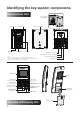
Identifying the key system components Camera Door Unit Removal of wall mounting plate Microphone Wall mounting plate Camera lens Push button Indication light Speaker Battery compartment Terminals for external 16V supply Note: - Visitor image will be impaired if the ambient backlight is very strong. - The video image is displayed in color during daytime or in well-lit area, but it is displayed in black and white at night or in dark area.
LCD Display 1 3 2 4 1 RF transmission condition 2 Excellent Battery power condition indicator (Portable Indoor Display Unit) Excellent • Battery status after 6 hours full charging. • Operation temperature at 20 deg. C • Continuous talking: 2 hours • Standby: 120 hours Good Weak Good None Low • Please charge the battery. Flat 3 Low battery indicator (Camera door unit) 4 Date and time indications The date and time is displayed at the bottom of the screen.
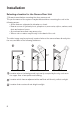
Installation Selecting a location for the Camera Door Unit 1) Areas to avoid when mounting the door camera unit The performance of the system may be affected when mounting the unit in the following areas • Areas that are subjected to vibration or shock. • Near a source of hydrosulphuric, phosphorus, ammonia, sulphur, carbon, acid, dust and noxious fumes. • An enclosed area that may cause echo • Where rain or water may directly hit the back of the unit.
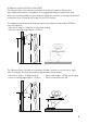
2) Camera position & Field of View (FOV) The Camera Door Unit can be mounted in a variety of locations. Review the information below before installation. It is suggested that you experiment with different mounting locations by holding the camera in position, pressing the doorbell pushbutton then checking the image on the LCD monitor. The diagrams below show an example camera position to view a visitor 500mm from the camera. 46 Deg. SHOOTING AREA 420mm • Camera tilt angle = 0 Deg.
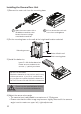
Installing the Camera Door Unit 1) Remove the main unit from the mounting base 1 Open the screw cover with a flat blade screwdriver, then loosen the screw using a crosshead screwdriver. 2 Lift to remove the main unit from the mounting base. 83.50mm 2) Fix the mounting base on the wall at the height and location selected Mounting screws Holes drilled in wall. Wall mounting plate. 3) Install the batteries Insert 6 x AA alkaline batteries. Please ensure to observe the correct +/- polarity as shown.
Angle adjustment lever Adjust camera view to the left (max. 15deg.) Adjust camera view to the right (max. 15deg.) Adjust camera view upwards (Max. 15deg.) Examples of possible camera adjustment Camera looks upwards Camera looks to the right Camera looks up & right 5) Re-fit the main unit to the mounting base • Ensure to secure with the screw and replace the screw cover.
B) Powering Existing Wired Doorbell Supply 1 Remove the Front Push and disconnect the wires. 2 Remove the cover from the Door Chime. 4 Finally, connect the wires from the front push to Camera Door Unit as shown in Diagram 2. CHIME BASE Transformer Supply Output REAR 16V TRANS FRONT DISCONNECT FRONT PUSH Diagram 1 FRONT PUSH 3 Disconnect the wire from the FRONT terminal in the chime base and re-connect it to the TRANS terminal (refer to Diagram 2).
Charging the Indoor Portable LCD Display unit. The indoor portable LCD display unit will need to be charged for approximately 6 - 8 hours before first use. 1) Install the battery pack 1 Remove the battery compartment cover. 2 Connect the battery connector to the socket located in the battery compartment. Seat the battery pack into the compartment. 3 Re-fit the battery cover - do not remove the foam cushion.
Wall mounting the Charging Cradle The Charging Cradle can either be used free-standing by use of the stand, or wall mounted as described below. Charging Cradle Release button Mounting plate Charging stand 1 Remove the stand by pressing down the release button located behind of the charging stand & pulling the cradle upwards. 2 Remove the mounting plate from the charging cradle. 4 Hang the Charging Cradle securely on the mounting plate and push it down so that it snaps in place.
Setting the Date and Time 1) Hold the “PLAY” button for 3 seconds. The date and time will appear with the YEAR highlighted as shown. Press the “UP” and “DOWN” arrows to select the year. 2) Press the “PLAY” button to move to the MONTH selection. Press the “UP” and “DOWN” arrows to select the month. 3) Press the “PLAY” button to move to the DATE selection. Press the “UP” and “DOWN” arrows to select the date. 4) Press the “PLAY” button to move to the HOUR selection.
Using the system Answering a caller 1) When a visitor presses the pushbutton, ring tones can be heard and the camera image shows on the LCD monitor. • A moving image of the visitor will appear for ten seconds followed by a still image. • The still image is stored in memory. • The “OFF” and “ANSWER” buttons will blink slowly. OFF Key ANSWER Key 2) Press the “ANSWER” button to talk to the visitor for up to 60 seconds. 3) Press the “OFF” button to finish the conversation.
Adjusting the Brightness & Volume The following adjustments can only be made while the system is operating. The easiest way to achieve this is to press the doorbell pushbutton and then press the “ANSWER” button. 1) Changing the Display brightness • Press the “BRIGHTNESS” button repeatedly until the desired display brightness is achieved - 5 levels are available.
Live Browsing This function allows you to monitor the view from the Door Camera on the LCD display at any time. Please note - the Live Browsing feature is only available if the Door Camera Unit is powered via mains power (see page 11 for details). The feature is disabled when powered by batteries. 1) Press the “BROWSE” button. OR 2) Press the “ANSWER” button. • The Camera Door unit is activated. • The Camera Door unit is activated.
Recording Video Images Automatic Recording Video images are automatically recorded each time a visitor presses the doorbell pushbutton. Each image has a date and time stamp that indicate when the visit occurred. The system can store a maximum of 163 images; when this limit is reached, the oldest image will be automatically deleted to allow a new image to be stored. By default, the number of images stored per visit is set to TWO; this can be changed as described below.
Using the SNAP feature The SNAP feature allows you to capture and store an image at any time whilst live video is on the screen of the LCD monitor. The image along with a time and date stamp is stored. 1) Press the “SNAP” button during live video. • The screen will indicate that recording is taking place. Viewing the recorded images The recorded images can be viewed at any time. 1) Press the “PLAY” button. • The most recently stored image will be displayed on the screen.
Other functions Night-time Illumination In low light night-time conditions, an infra-red LED light will illuminate on the Camera Door unit to improve the quality of the transmitted image. Note that the image will be displayed in black & white under these conditions. Pairing The Door Camera and LCD Monitor are “paired” by a coding system so they will only communicate with each other. This encoding provides a secure system so your video and audio are not shared with others.
Replacing the rechargeable battery pack After a prolonged period of use you may have to replace the battery pack. If the battery does not recharge completely or does not hold a charge you will need to replace it. Use a “THB-121” battery for replacement. Follow the procedure below to replace the battery pack. 1) Remove the battery cover. Low battery 2) Unplug and remove the old battery pack. (Follow the instructions below for recycling of the old battery).
Caring for your system • Unplug the charging cradle before cleaning the unit. • Wipe the surfaces with a soft, dry cloth. Slightly moisten the cloth if required. • Wipe the charging terminals in the charging cradle with a soft cloth once a month. Charging time may be longer if the terminals are dirty.
Troubleshooting Symptoms Probable causes & solutions Subjects show up in black and white or background shows up in greenish. Is the background dark, such as at night time? • Subjects shows up as black and white due to color-dulling when it becomes dark. Also could appear “greenish” in areas covered by outdoor lights. This is normal at night when lighting is provided by the IR LED in the Door Camera unit. The visitors face is dark in the video image.
Troubleshooting Symptoms Probable causes & solutions A howling noise distorts the sound. If the LCD Monitor is too close to the Door Camera unit, a howling sound can occur. • Re-locate the LCD Monitor further away from the Door Camera unit. The ring tone cannot be heard. Has the battery run out of power? • Please charge the battery. The charging lamp does not illuminate when the LCD Monitor unit is placed in the charging cradle.
IQ America Two Year Warranty This is a “Limited Warranty” which gives you specific legal rights. You may also have other rights which vary from state to state and province to province. For a period of two years from the date of purchase, any malfunction caused by factory defective parts or workmanship will be corrected at no charge to you. To obtain a refund or a replacement, return the product to the place of purchase.