
Data Sheet_12L_12D_12D7_ Limit Switch Actuators_ENG_V1

Data Sheet 12L/12D Series Limit Switch Actuator_ENG_V1.0
Page 2 / 5
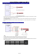
Wiring Diagram for 12L / 12D Series Limit Switch mightyZAP Actuator
[Basic Connection]
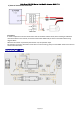
<Normal Rotation Connection >
< Counter Rotation Connection >
For actuator control, direction control is performed by applying forward and reverse voltage to the exposed wire. The DPDT
switch makes it easy to change the direction of motion.
The voltage application range is 7V~13VDC, but the rating is 12V, so the power is weakened and the speed is slowed down
at the voltage below 12V.
If voltage over 13V is applied, the circuit and motor may be damaged. Be sure to apply voltage below the rated voltage of
12V.
How to apply DPDT Switch or External Micro Limit Switch
1) DPDT Switch Connection
[Description]
The DPDT switch has two built-in SPDT switches to perform the same operation.
The operation of the switch according to the above wiring diagram is as follows.
Pay attention to wiring to avoid short circuit due to incorrect wiring. (The pins of the DPDT switch must not be in
contact with each other)
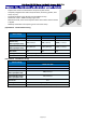
Switch Status
RED(3)
BLACK(4)
Motion
▲
VCC
(1)
GND
(2)
CW
○
OPEN
OPEN
STOP
▼
GND
(5)
VCC
(6)
CCW