
User's Manual


FUNCTION SETTING
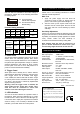
SW1 DIP switch is available for all function settings of
the detector. Please refer to the following instructions
for setting options.
Function Setting Indication
SW#
1 2 3 4 5 6
Function
Setting
Pulse
Count
Trigger
Count
LED
ON/OFF
Alarm
Output
MW Sensitivity
ON 3 ON ON NC
OFF 1 OFF OFF NO
(Refer to next
table)
Microwave Sensitivity Setting
MW
Sensitivity
60% 80% 100% 120%
Detection
Coverage
(@3m high)
4x4m 6x6m
8x8m
(default)
12x12m
Switch
Setting
1. Pulse Count
The DP-363 features intelligent pulse count in its PIR
sensor which can effectively prevent false alarms
cause by environmental interference. If it is installed at
the places with rapid temperature change or unknown
electrical interference, DIP switch #1 which controls
the PIR pulse count can be set to ON position for 3
pulses to increase the detection reliability.
2. Trigger Count
When pulse count is already set on, and the detector
still experiences false alarm caused by unknown factor,
then “Trigger Count” can be enabled. With trigger
count enabled, the detector will hold the alarm output
for a short period of time and release the alarm signal
only when a true intrusion is verified by sophisticated
signal processing software.
Warning: Once the trigger count is enabled, the
alarm output will be slower than normal. Thus,
walk test must be conducted to ensure that
detector not to miss catching the intrusion.
3. LED Indication
The LED of DP-363 indicates the operation status of
the detector. When the green LED lights up, it means
the MW sensor is active. When the red LED lights up,
it shows the alarm output (also represents the infrared
sensor is active). If it is necessary to disable the LED
indication, just set DIP switch #3 to OFF position.
WALK TEST & ADJUSTMENT
Please refer to the following instructions to conduct
walk test and MW adjustment.
Walk Test
1. Apply DC power supply and wait about 60
seconds for sensor to warm up. During warm up
period, both red and green LEDs will light up.
2. After the warm up time expires, walk across the
detection area at normal speed. Check if the red
and green LED turn on/off following by tester’s
walk/stop.
Sensitivity Adjustment
If there is no movement within the detection range and
the green LED remains on, this means that MW sensor
is probably over sensitive (usually appears in a smaller
room). Please reduce the MW sensitivity in
accordance with the MW sensitivity setting table.
Note: Regular walk test must be carried out, as
part of routine maintenance at least once a year.
The mounting height should be at least at 2.4m.
SPECIFICATIONS
MW frequency 10.525GHz
MW output power 10dBm EIRP
Power supply 9
~
16VDC
(12 VDC nominal)
Current drain 17mA@12VDC
Infrared sensor Omni-directional, dual element,
low noise
Microwave sensor DRO w/m micro strip antenna
Mounting height 2.4
~
3.6m
Alarm period 2
~
4 sec.
Alarm output NC/NO, selectable, 30VDC,
0.2A max.
Warm up period 60sec
.
Red/Green LED on
Alarm output LED Red, can be disabled
MW sensor LED Green, can be disabled
Tamper protection NC, cover open activates
Pulse count PIR 1/3, selectable
Op. temperature -20° C
~
55° C (-4°F~131°F)
Dimensions 110 (dia.) x 44mm (H)
06/07’ 058-36321-001
FCC ID: NRIDP363
This device complies with Part 15 of the FCC Rules.
Operation is subject to the following two conditions:
(1) This device may not cause harmful interference,
and
(2) This device must accept any interference received,
Including interference that may cause undesired
operation.
l The black blocks
indicate switch position.
l The left shows factory
default setting.