
Users Manual


INTRODUCTION
P/N: 058-60901-001Printed in Taiwanwww.irtec.com
This product may be covered by one or more U.S. patents or patent applications.
Please visit www.irtec.com for more information.
Line Voltage OS-NET Sensor
ON-LRD-309S
INSTALLATION INSTRUCTIONS
Risk of Electric Shock - Disconnect power supply before
servicing.
Do NOT touch the square window of infrared sensor under
the lens assembly.
Open Type Photoelectric Switches.
Install this device in accordance with electrical codes and
protect with circuit breaker.
Install the sensor at least 1 ft. away from any occupant.
Cycling the power to the sensors will cause failure over time.
WARNING & CAUTION
Risque de choc électrique - Débranchez l'alimentation
avant l'entretien.
Ne PAS toucher la fenêtre carrée de capteur infrarouge
sous l'ensemble de l'objectif.
Ouvrir Type commutateurs optoélectroniques.
AVERTISSEMENT & PRUDENCE
Indoor dry location use only
Utilisation a L'interieur Uniquement
The ON-LRD-309S is a low profile OS-NET Sensor (ONS)
packed with multiple sensing control functionalities
including occupancy/vacancy sensing, daylight
harvesting, bi-level StepDIM or continuous SmartDIM,
and wireless mesh networking capability for top-notch
intelligent lighting control.
Being a member of Mini ONS, this sensor can be
integrated with general office luminaires through a 1”
hole. A flat lens provides excellent detection to the office
activities within its coverage. With ON-LRD-309S, you
can effortlessly achieve code-compliant, energy efficient
smart lighting control through a wireless sensor mesh
network effortlessly deployed while installing the OS-NET
enabled luminaires in commercial environments.
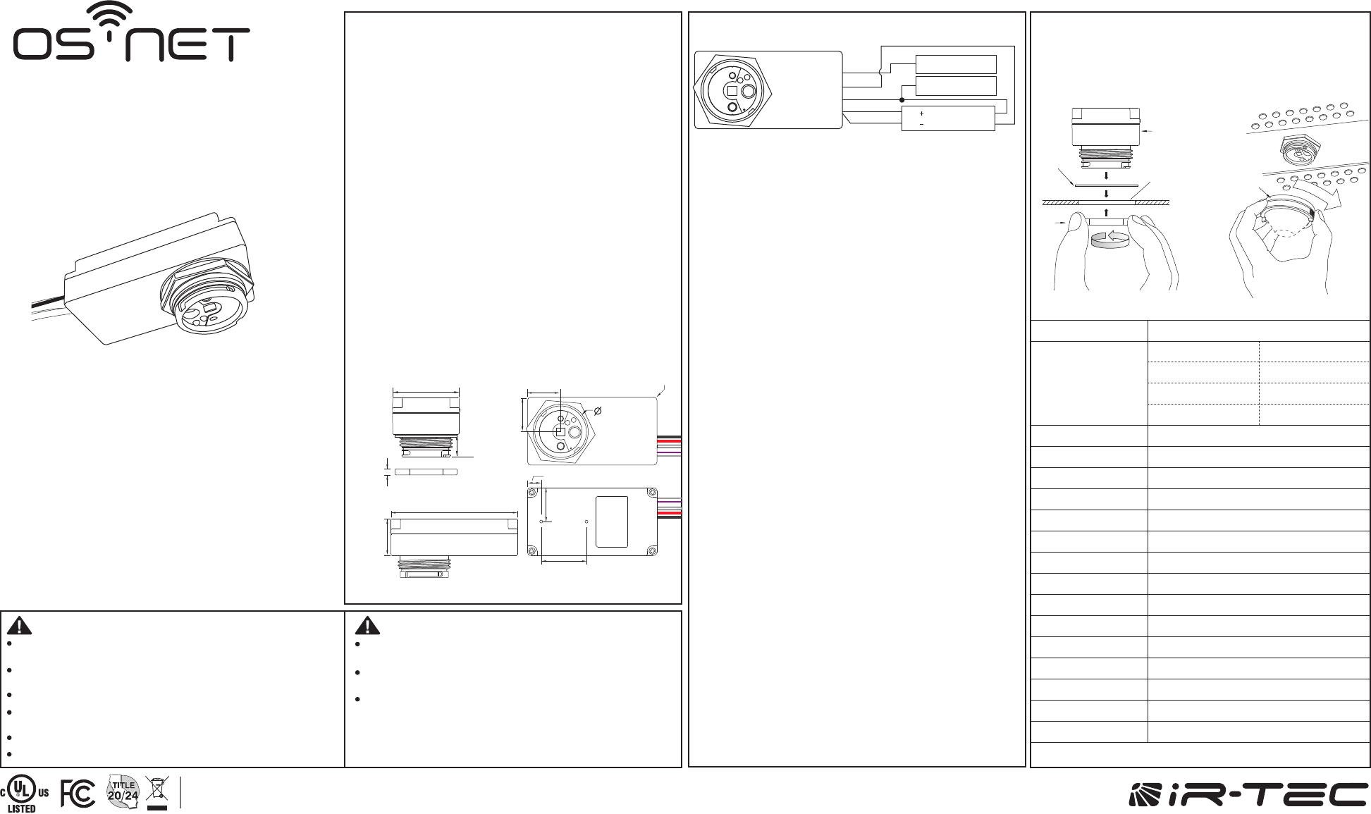
DIMENSIONS
MOUNTING
Use 0/1-10V dimmable driver/ballast to enable
dimming control.
Ensure to connect the LINE and NEUTRAL wires
correctly. Reverse connection may damage the
sensor permanently.
Ensure TOTAL isolation between DIM+/DIM- and
GROUND of line voltage to avoid damaging the
sensor.
Always conduct factory test with GROUND
connected.
1.
2.
3.
4.
NOTE:
WIRING DIAGRAM
Neutral
Line
DIM
DIM
N
L
Gray
Violet
Red
White
Black
BALLAST
LED DRIVER
APPLICATION NOTES
The sensor is more sensitive to the movements
“crossing” the detection zones than “toward” or
“away” the sensor unit. To obtain better sensitivity,
avoid placing the sensor in line with occupant path.
The closer the movement is to the sensor, the more
sensitive the sensor is. The higher the sensor is
installed, the larger movement is required to be
detected.
Ensure to place the sensor at least at 1.5m (5 ft.)
away from air supply ducts as rapid air flow may
cause false activations.
The sensor cannot “see” the movements behind
obstacles, such as tall furniture, shelf, glass or
partitions. Avoid placing the sensor where
obstructions may block the sensor’s line of sight.
The partition of workstation could block the sensor
view to occupant movements, it is best to place the
sensor over the intersection of workstation. For large
open office, place multiple sensors so that there is
overlap coverage with each adjacent sensor.
To obtain optimal wireless communication range,
avoid enveloping the sensor with a metallic
enclosure.
1.
2.
3.
4.
5.
6.
PRELIMINARY
8.5mm (0.33”)
28mm (1.1”)
21mm
(0.83”)
33.2mm
(1.31”)
(thread tip)
R2mm
(0.08”)
21mm
(0.83”)
21mm (0.83”)
80mm (3.15”)
23mm
(0.91”)
14mm
(0.6”)
42mm (1.65”)
4mm
(0.16”)
The sensor can be integrated with lighting fixture through
a round hole with 34mm (1.34”) diameter.
Lens
Assembly
Ø34mm
(1.34”)
1.0~2.8mm
(0.04~0.11”)
Nut
Rubber
Gasket
Sensor
SPECIFICATIONS
Power supply
Infrared sensor
Dim control
HIC protection
Wireless protocol
Radio frequency
Number of Channel
Radio range
Radio Power Output
Detectable speed
Mounting height
Detection range
Remote range
Op. humidity
Op. temperature
Dimensions
120/277VAC, 50/60Hz
Digital quad-element pyroelectric sensor
0-10V, ±5%, isolated, max 25mA
Max. 80A for 16.7msec.
Modified Zigbee Light Link (ZLL)
2405~2475MHz
15ch
15/90 m @indoor/outdoor, open space
5.63dBm
0.15 ~ 3 m/sec. (0.5~10 ft./sec.)
Subject to the lens applied
As per lens applied and mounting height
Typ. 10 m (33 ft), indoor with no backlight
Max. 95% RH
-40°C~70°C (-40°F~158°F)
80x42x37mm (3.15”x1.65”x1.46”)
Maximum Load
-Incandescent/Halogen
-Fluorescent Ballast/CFL
-Ballast Electronic (LED)
120VAC
800/*500W(VA)
800/*500W(VA)
540/*500VA
1200/*750W(VA)
1200/*750W(VA)
1200/*750VA
277VAC
*Max load for operating temperature at 55°C~70°C(131°F~158°F)