
Datasheet


IR2184
(
4
)(
S
) & (PbF)
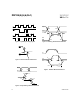
Typical Connection
HALF-BRIDGE DRIVER
Features
•
Floating channel designed for bootstrap operation
Fully operational to +600V
Tolerant to negative transient voltage
dV/dt immune
•
Gate drive supply range from 10 to 20V
•
Undervoltage lockout for both channels
•
3.3V and 5V input logic compatible
•
Matched propagation delay for both channels
•
Logic and power ground +/- 5V offset.
•
Lower di/dt gate driver for better noise immunity
•
Output source/sink current capability 1.4A/1.8A
•
Also available LEAD-FREE (PbF)
IR21844
IR2184
www.irf.com 1
Data Sheet No. PD60174 revG
(Refer to Lead Assignments for correct
configuration). This/These diagram(s) show
electrical connections only. Please refer to
our Application Notes and DesignTips for
proper circuit board layout.
Packages
14-Lead PDIP
IR21844
8-Lead SOIC
IR2184S
14-Lead SOIC
IR21844S
8-Lead PDIP
IR2184
Description
The IR2184(4)(S) are high voltage,
high speed power MOSFET and IGBT
drivers with dependent high and low
side referenced output channels. Pro-
prietary HVIC and latch immune
CMOS technologies enable rugge-
dized monolithic construction. The
logic input is compatible with standard
CMOS or LSTTL output, down to 3.3V
logic. The output drivers feature a
high pulse current buffer stage designed for minimum driver cross-conduction. The floating channel can be
used to drive an N-channel power MOSFET or IGBT in the high side configuration which operates up to 600
volts.
IR2181/IR2183/IR2184 Feature Comparison