User Manual for the CARESTREAM TRIMAX 35C Detector Publication No.
All rights reserved. No part of this manual may be reproduced or copied in any form by any means—graphic, electronic, or mechanical, including photocopying, typing, or information retrieval systems—without written permission.
1 Notices and Conventions The information herein is based on the experience and knowledge relating to the subject matter gained by Carestream Health, Inc. prior to publication. No patent license is granted by this information. Carestream Health reserves the right to change this information without notice, and makes no warranty, express or implied, with respect to this information.
Notices and Conventions CAUTION: Federal law restricts this device to sale by or on the order of a physician. CAUTION: If you witness or become aware of a potential safety issue with this equipment, take the appropriate safety measures and report this to your Carestream Service representative immediately.
Notices and Conventions Disclaimer • Carestream shall not be liable to the purchaser of this product or third parties for any damage, loss, or injury incurred by the purchaser or third parties as a result of fire, earthquake, any accident, misuse, or abuse of the product. • Carestream shall not be liable for any damage, loss, or injury arising from unauthorized modifications, repairs, or alterations to the product or failure to strictly comply with Carestream’s operating and maintenance instructions.
Notices and Conventions 1–iv AJ4310 | 2019-08-13
Contents 1 Notices and Conventions Disclaimer...................................................................................................................................... 1-iii 1 Safety and Regulatory Information Symbols .......................................................................................................................................... 1-1 Cautions ................................................................................................................................
Contents Set the Connection Mode .......................................................................................................... Wireless Client Mode............................................................................................................ Wireless AP Mode................................................................................................................. Shortcuts ......................................................................................................
1 Safety and Regulatory Information Symbols Symbols and Conventions WARNING: This is used to identify conditions under which improper use of the product may cause death or serious personal injury. This is used to indicate a prohibited operation. This is used to indicate an action that must be performed.
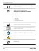
Safety and Regulatory Information This indicates that the product has passed CE certification and is followed by the CE number. This is used to identify the manufacturer’s series number, which is after, below, or adjacent to the symbol.
Safety and Regulatory Information This indicates operational temperature limits. This indicates storage temperature limits. This indicates the product radiates a wireless signal. Package symbol: Fragile Package symbol: Keep away from sunlight. Package symbol: Keep dry. This indicates the humidity limits.
Safety and Regulatory Information Keep the product upright. Do not roll the transportation packaging. This indicates the stacking limit number. This indicates a Type-B applied part.
Safety and Regulatory Information Cautions Environment for Installation and Use Environment for Installation and Use WARNING: Do not use or store the product near flammable chemicals such as alcohol, thinner, benzene, etc. Chemicals that are spilled or evaporated may result in fire or electric shock through contact with electric parts inside the product. Also, some disinfectants are flammable. Be sure to take care when using them.
Safety and Regulatory Information CAUTION: Do not install the product in any of the locations listed below to avoid failure, malfunction, falling, fire, or injury.
Safety and Regulatory Information Power Supply WARNING: Do not operate the product with a power supply other than the one indicated on the rating label to avoid fire or electric shock. WARNING: Do not handle the product with wet hands to avoid electric shock that could result in death or serious injury. Power Supply WARNING: Do not place heavy object on cables and cords. Co not pull, bend, bundle, or step on them to prevent damage to the sheath. Do not alter them.
Safety and Regulatory Information WARNING: Do not connect multiple portable socket outlets or extension cords to the system to avoid fire or electric shock. Power Supply WARNING: Connect this product only to a power supply with protective earth to avoid fire or electric shock. WARNING: Do not use the adapter cord when connecting the panel to a patient.
Safety and Regulatory Information WARNING: Securely insert the power cord into the AC outlet to avoid a contact failure. If a contact failure occurs or if metal objects come in contact with the exposed metal prongs of the plug, fire or electric shock may result. Power Supply WARNING: Be sure to turn off the power before connecting or disconnecting the cords to avoid an electric shock that could result in death or serious injury. WARNING: Be sure to hold the plug or connector to disconnect the cord.
Safety and Regulatory Information Handling WARNING: No modification is allowed. Never disassemble or modify the product to avoid fire or electric shock. The product incorporates parts that may be hazardous or cause electric shock Touching them may cause death or serious injury. Handling WARNING: Do not place an object on top of the product. The object may fall and cause an injury. Metal objects such as needles or clips that fall into the product or spilled liquid may result in fire or electric shock.
Safety and Regulatory Information CAUTION: Do not spill liquid or chemicals onto the equipment. Do not allow an injured patient’s blood or body fluids contact with the equipment. Doing so may result in fire or electric shock. Handling In such a situation, protect the equipment with a disposable cover as necessary. CAUTION: For safety Turn OFF the power and remove the plug for all equipment when not used. CAUTION: Handle the product carefully. Do not submerge the product in water.
Safety and Regulatory Information CAUTION: Do not place excessive weight on the panel to avoid damage to the internal image sensor and an incorrect image. Patients stand on the product temporarily, and the intended weight can be 135 kg.
Safety and Regulatory Information CAUTION: Be sure to use the product on a flat surface to prevent the product from bending and doing damage to the internal image sensor. Be sure to securely hold the product while using it in an upright positions to prevent the product from tipping or flipping over, resulting in injury to the user or patient damage to the inner device. Handling Keep the same pressure on the product when acquiring an image to avoid an incorrect image.
Safety and Regulatory Information CAUTION: Handling 1–14 • Do not use the product close to fire or in high temperature. • Do not invert the positive and negative poles. • Do not allow the product to make contact with metal to avoid a short circuit. • Do not insert sharp objects into the battery. • Do not strike the battery. • Do not stand on the battery. • Do not use the battery outside of the guidelines. • Do not dispose of the battery or change the inner structure.
Safety and Regulatory Information Maintenance and Inspection WARNING: Maintenance and Inspection • Turn off the power of the product and disconnect the power cord of the adapter before cleaning. • Never use alcohol, ether, and other flammable cleaning agent for safety. Never use methanol, benzene, and acid to avoid corrosion on the equipment. • Do not place the product in liquid.
Safety and Regulatory Information When a Problem Occurs When a Problem Occurs WARNING: If any one of the following occurs, immediately disconnect the power cord of the adapter or battery, and contact your sales representative or local dealer: • When there is smoke, an odd odor, or abnormal sound • When liquid has spilled into the equipment or a metal object has entered through an opening • When the product has been dropped and damaged Medical Equipment Classification Type of protection against elec
Safety and Regulatory Information Standards ISO 13485:2016 Medical devices — Quality management systems — Requirements for regulatory purposes IEC 60601-1:2005/AMD1:2012 Medical electrical equipment — Part 1: General requirements for basic safety and essential performance IEC 60601-1-2:2014/EN60601-1-2:2015 Medical electrical equipment — Part 1-2: General requirements for basic safety and essential performance — Collateral standard: Electromagnetic disturbances v Requirements and tests IEC 60601-2-54
Safety and Regulatory Information CAN/CSA-C22.2 No.
Safety and Regulatory Information Emissions and Immunity Compliance to the IEC60601-1-2 Standard Electromagnetic Emissions Emissions Test Compliance Electromagnetic Environment RF emissions CISPR 11 Group 1, Class B The TRIMAX 35C Detector uses RF energy only for its internal function. Therefore, its RF emissions are very low and are not likely to cause any interference in nearby electronic equipment.
Safety and Regulatory Information Proximity Fields From RF Wireless Communications Equipment Test Levels Test Frequency (MHz) Band (MHz) 385 380–390 Pulse modulation 18 Hz, 27 V/m 450 430–470 FM, ±5kHz deviation, 1 kHz sine, 28 V/m 704–787 Pulse modulation 217 Hz, 9 V/m 800-–960 Pulse modulation 18 Hz, 28 V/m 1700–1990 Pulse modulation 217 Hz, 28 V/m 2400–2570 Pulse modulation 217 Hz, 28 V/m 5100–5800 Pulse modulation 217 Hz, 9 V/m Professional healthcare facility environment 710 745 78
Safety and Regulatory Information Test Levels Emissions Test EMC Standard Professional healthcare facility environment Surges Line-to-ground IEC 61000-4-5 ±0.5 kV, ±1kV, ±2 kV Conducted disturbances induced by RF fields IEC 61000-4-6 3 V, 0.15 MHz–80MHz 6 V in ISM bands between 0.15 MHz and 80 MHz 80 % AM at 1 kHz Voltage dips IEC 61000-4-11 0 % UT; 0.
Safety and Regulatory Information Reference Cables Provided Against EMC Recommended Cable Length Shielded or Unshielded Number Cable Classification AC Power Cable 3m Unshielded 1 pcs AC Power DC Power Cable 3.
Safety and Regulatory Information Radio Frequency Compliance Country Item U.S.A FCC Part 15.107 Sub part (b) / 15.109 (g) Sub part B FCC Part 15 Sub part E 15.407 FCC Part 15 Sub part C 15.247 European Union ETSI EN 301 489-1 V1.8.1 (EMC) ETSI EN 301 489-17 V2.1.1 (EMC) EN 300 328 V.1.7.1; EN 301 893 V1.6.1 (RF) EN 62311:2008 (RF Exposure) ETSI EN 300 328 V1.7.1; EN 301 893, V1.5.
Safety and Regulatory Information Battery Safety Standards Standards Description CAN/CSA E62133:13 1st Ed. Rev. Secondary cells and batteries containing alkaline or other non-acid electrolytes — Safety requirements for portable sealed secondary cells, and for batteries made from them, for use in portable applications First Edition UL 62133, 1st Ed. Rev.
Safety and Regulatory Information Intended Use and Essential Performance Intended Use TRIMAX 35C is indicated for digital imaging solutions designed for providing general radiographic diagnosis of the human anatomy. It is intended to replace radiographic film/screen systems in all general purpose diagnostic procedures. This panel provides digital X ray imaging for diagnosis of disease, injury, or any applicable health problem.
Safety and Regulatory Information 1–26 AJ4310 | 2019-08-13
2 Overview The TRIMAX 35C Detector is a cassette-size, wireless x-ray flat panel detector based on amorphous silicon thin-film transistor technologies. It is developed to provide the highest quality of radiographic images with an active matrix of 2304 × 2800 with 150 um pixel pitch. The detector supports wireless communication between the panel and the workstation and is powered by an internal battery. Scope This manual contains information about the TRIMAX 35C.
Overview Components and Specifications Product Components Component Description Detector Figure 1: External Signals Figure 2: Input Control Panel 2–2 AJ4310 | 2019-08-13
Overview Item Description Notes A DC jack Not used B Ethernet port For service C Detector indicator Detector indicator of control panel D Power button Power button of control panel E Mode button Mode switch F Antenna Battery Item Description A Battery label B Battery interface C Pilot pin D Indicator AJ4310 | 2019-08-13 Notes 8 pin battery connector Installation direction indicator 2–3
Overview Battery Charger Item Description Notes A Battery Interface A 8 pin battery connector B Battery Interface B Not used C Battery Interface C Not used D Indicator The indicator definition is as follow E The limit ball plug / F Hand Pull Position / G AC Jack 220V (ac) input Battery Charger Indicator Item 2–4 Name A Power Indicator B Charging Indicator C Charge Full Indicator AJ4310 | 2019-08-13
Overview X Indicator Operating Status All off No power input A indicator on • AC power input • Multiple batteries inserted A indicator on B and C alternately blink 2 times Battery insertion self test A and B indicator on Battery charging A and C indicator on Battery capacity full, charging stops A indicator on B and C alternately blinking Battery is not charging properly Two or more batteries charging cannot be charged at the same time.
Overview Product Specifications Detector Item 2–6 Specifications Model TRIMAX 35C Image Sensor a-Si (amorphous silicon) TFT Pixel Size 150 μm Active Array 2304 x 2800 Active Area (H x V) 345.6 x 420.0 mm (13.6 x 16.5 in.) Gray Scales 16 bit Spatial Resolution 3.3 Lp/mm Image Acquisition Time (Wireless) Both AP Mode and Client Mode Preview acquisition time: 3 sec. Processed acquisition time: 5 sec. Cycle Time Min. 8 sec. Power Consumption Max. 18 W Dimension (L × W × H) 460.
Overview Battery Item Specifications Model Battery-KV Rated capacity Typ. 4180 mAh @ Discharge 0.2C Nominal voltage 10.8 V Charge voltage 12.6 ± 0.05 V Discharged end voltage 9V Charging method CC-CV Operating temperature Charge 0–60 °C (32–140 °F) Discharge 0–60 °C (32–140 °F) Storage temperature ≤3 month -20 °- +45 ° (-4–113 °F) ≤6 month -20°- +35 ° (-4–95 °F) Relative humidity 5 %~95 % Dimension (L × W × H) 210 x 115 x 7.5 mm Weight 0.28 kg (0.
Overview Battery Charger Item Specifications Model Charger-Combo Simultaneous Charging 1 Battery Pack Full Charging Time ≤ 3 hr Rated Power Supply 90~264 V (ac) Dimension (L × W × H) 240.0 x 184.0 x 38.0 mm (9.4 x 7.2 x 1.52 in.) Weight 0.55 kg (1.2 lb) Power Supply Item Specifications DC Power 24V (dc), 0.75A Battery Package 10.8V (dc), 1.6A The product must be used with the approved adapter and CB certificate number SG PSB-MD-00191.
Overview Wireless Communication Item Specifications Wireless Standard IEEE 802.11 a/b/g/n/ac Frequency Range 2.412~2.472 GHz: ch1~ch13 5.18~5.22 GHz: ch36~ch48 5.745~5.85 GHz: ch149~ch165 Data Transmission Rate 802.11b: Max. 11 Mbps 802.11a/g: Max. 54 Mbps 802.11n: Max. 300 Mbps (MIMO 2x2) 802.11ac: Max. 867 Mbps(MIMO 2x2) Modulation 802.11b: CCK, DQPSK, DBPSK 802.11a/g/n: 64 QAM, 16 QAM, QPSK, BPSK 802.11ac: 256 QAM, 64 QAM, 16 QAM, QPSK, BPSK Transmission Power Max.
Overview Mechanical Outlines Use Environment Temperature Temperature Change Humidity Atmospheric Pressure Pressure Change Operating 5–35 °C (41–95 °F) < 1k/min 10 %–90 % RH 700–1060 hPa <10 kp/min (1 kp=1.0197E-5Pa) Storage -20–55 °C (-4–131 °F) < 1k/min 5 %–95 % RH 700–1060 hPa <10 kp/min (1 kp=1.0197E-5Pa) TRIMAX 35C detectors shall operate at a specified altitude of not more than 3000.0 m (9842.5 ft). The environment specific is only for the detector.
Overview IT Network Purpose for IT-network Transmission of image data and command/status communication between the detector and the workstation. Required Features Wireless communication follows IEEE 802.11a/b/g/n/ac protocol. It works on 2.4 GHz and 5 GHz. It supports at least 2 routers.
Overview Item Specifications Data Transmission Rate 802.11b: Max. 11 Mbps 802.11a/g: Max. 54 Mbps 802.11n: Max. 300 Mbps (MIMO 2x2) 802.11ac: Max. 867 Mbps (MIMO 2x2) Modulation 802.11b: CCK, DQPSK, DBPSK 802.11a/g/n: 64 QAM, 16 QAM, QPSK, BPSK 802.11ac: 256 QAM, 64 QAM, 16 QAM, QPSK, BPSK Security WPA, WPA-PSK, WPA2, WPA2-PSK, WEP 64 bit, and 128 bit Intended Information Flow The detector sends the acquired image data to the workstation. The workstation sends the user's commands to the detector.
Overview • Connection of additional items to the IT network • Disconnecting of items from the IT network • Update of equipment connected to the IT network AJ4310 | 2019-08-13 2–13
Overview Service Information Product Lifespan The estimated product lifetime is up to 7 years under appropriate regular inspection and maintenance (battery 5 years). Regular Inspection and Maintenance In order to ensure the safety of patients and operator, and to maintain the performance and reliability of the panel, be sure to perform regular inspections at least once a year. If necessary, clean the panel, make adjustments, or replace consumables such as fuses etc.
Overview Disposal CAUTION: Do not dispose of this product with your residential or commercial waste. Improper handling of this type of waste could have a negative impact on health and on the environment. Some countries or regions, such as the European Union, have set up systems to collect and recycle electrical or electronic waste. Contact your local authorities for information about dropping off waste products for recycling.
Overview 2–16 AJ4310 | 2019-08-13
3 Installation Panel Installation Install the Detector Battery The detector can be powered by the battery package or DC power. The detector will be activated as soon as power is supplied and will power off as soon as power is removed. 1. Make sure that the connectors for the battery and battery compartment are aligned.
Installation 2. Slide the battery into the battery compartment. Note: Make sure the battery level is >10 % of full capacity. 3. Slide the two battery lock levers toward the center of the detector.. Power on the Detector On the control panel, the power button is used to power the detector on and off. To power on the detector, press and hold the power button for 4 seconds. The detector must either have a battery installed with >10 % charge or have the DC power connected.
Installation To reset the detector, press and hold the power button for 8 seconds. Power Indicator After booting up, the user can check the status LED indicator.
Installation Operating Status Power Indicator Lighting Status Operating Battery Capcity DC Input Green Fast Blinking Power OFF ≥95 % and <100 % Yes OFF Power OFF =100 % Yes Link Indicator Power Indicator Off Lighting Status Description • Shut down • Wired connection broken and wireless connection not ready Green On Wired connection is built Blue On • Client mode, wireless connection is built • AP mode, wireless AP is ready Blue Blinking Client mode, no connection is built Green
Installation Status Indicator Power Indicator Lighting Status Off Description • Shut down • Exposure prohibit Green On Exposure enable Green Blinking Exposure enable Orange On Error Orange Blinking Safety mode Mode Indicator Power Indicator Off Lighting Status Description • Shut down • Wired connection is built Green On AP mode, wireless AP is ready Blue On Client mode, wireless client is ready Blue and Green Blinking Initialization AJ4310 | 2019-08-13 3–5
Installation Button Function Power Action Mode Note FPD Status Power ON Short hold Forced restart No action Hold for 4 seconds Long hold No action Hold for more than 7 seconds. Release the power button when the power indicator is ON. Press 3 times No action Release after two short presses (interval < 1second).
Installation Install the Detector Battery Charger 1. Remove the battery from the battery charger. 2. Insert battery into battery charger in the orientation shown below. 3. Press the battery down into the battery compartment.
Installation Detector Battery Lock and Activation To ensure the safety of the battery during transportation or storage, the battery can be set to ship mode where it is locked and will not provide any voltage output. Enter Ship Mode Method Steps Factory configuration 1. Connect the adapter to the detector and power it on. Web write in 2. Connect the other end of the adapter to the PC. 3. Insert the battery into the detector. 4. Open a web browser and enter the following address: http://10.0.1.
Installation Method Adapter + FPD Steps 1. Connect the adapter to the detector and power it on. 2. Insert the battery into the detector. 3. Press the power button for approximately 4 seconds to shut down the detector. 4. In the shutdown state, press the power button 3 times to exit ship mode. Charger 1. Power on the charger. 2. Insert the battery into the charger for 3 to 5 seconds to exit ship mode.
Installation 3–10 AJ4310 | 2019-08-13
4 Operation Notes for Using Do the following to ensure that the detector functions correctly. Before Exposure Inspect the detector daily and confirm it is working properly. Check that there is no condensation on the any of the surfaces of the detector. Condensation can be caused by the sudden heating of the room in cold areas. If this occurs, wait until the condensation evaporates before performing an exposure or problems may occur with the quality of captured images.
Operation Cleaning, Disinfection, and Sterilization of Patient Contact Surfaces To prevent the risk of infection, wipe the patient contact surfaces after every examination with a nonflammable disinfectant, such as benzalkonium chloride or benzalkonium bromide. For details on how to sterilize, consult a specialist. CAUTION: Do not spray disinfectants or detergents directly onto the detector. To prevent damage to the surface of the detector, wipe with a cloth slightly dampened with a neutral detergent.
Operation Detector Position To prevent abnormal light lines, place the detector behind the patient in the orientation shown below.
Operation 4–4 AJ4310 | 2019-08-13
A Appendix Software and Settings Main Interface Item Description Function 1 Home Home page, shows the list of the detectors 2 Acquire Acquire images, free for use after connecting the detector 3 SDK Configure UI for SDK, free for use after connecting the detector 4 Detector Configure UI for detector, free for use after connecting the detector 5 Calibrate Calibrate UI, for generation and management of the calibration template 6 Local File Image management, free for use at any time 7
Appendix Item Description Function 8 Close Disconnect the detector 9 Add Add the instance for one detector 10 Remove Delete the instance for one detector 11 Syncbox Manage the syncbox Message Box Status Box Tab Description SN Serial number of the detector Status Status of the detector, busy or ready Task The task that is currently being executed Message Information Remaining power of the battery, shown as a percentage A–2 AJ4310 | 2019-08-13
Appendix Progress Bar If the progress bar • Is green while taking an x-ray, the image quality is acceptable • Is not green while taking an x-ray, the image quality will be degraded General Settings Parameter Description Can be Modified Product No. Type number of the detector No Sub Product No. Sub-type of the detector No Serial No.
Appendix Parameter Description Can be Modified Main MB CPU Version Version of the MB CPU of Main FPGA No MCU Version Version of the firmware of MCU No Arm Version Version of the App of ARM No Kernel Version Version of the Kernel of ARM No Inner Subflow Sub work-flow Yes Prep CapMode Reserved No Self CapEnable Reserved Yes Self Cap Span Time Should not be modified; keep the original value Yes Trigger Mode Trigger mode Yes Sequence Interval Time Should not be modified; keep the
Appendix Parameter Description Can be Modified Hvg Prep On Reserved Yes Hvg XRay Enable Reserved Yes Hvg XRay On Reserved Yes Tube Ready Time Reserved Yes Image Pkg Gap Time Reserved Yes Out Mode Cap Trigger Reserved Yes AJ4310 | 2019-08-13 A–5
Appendix SDK Settings Parameter Description Can be Modified Host IP IP Address of local workstation Yes Host Port Port of local workstation Yes Ftp Download Host IP FTP download server IP; keep the same as Host IP Yes Ftp Download Host Port FTP download server Port; keep the same as Host Port Yes Ftp Upload Host IP FTP upload server IP; keep the same as Host IP Yes Ftp Upload Host Port FTP upload server Port; keep the same as Host Port Yes A–6 AJ4310 | 2019-08-13
Appendix Network Settings Button Description Add Add the information of SSID and the AP Key Del Delete the information of SSID and the AP Key Up Move up the AP information Down Move down the AP information Select Select the AP Read Config Read the parameters of the AP information when the detector is set as AP Write Config Write the parameters of the AP information when the detector is set as AP Read Wifi Status Read the WIFI status of the current detector Scan from FPD Scan the AP AJ4
Appendix Operating Modes The main purpose of the TRIMAX 35C is to acquire x-ray images. Most importantly, the panel works in synchronization with the x-ray generator. TRIMAX 35C acquires x-ray images in three ways: Software Mode, Inner2 Mode, and FreeSync Mode. Software Mode Block Diagram Software mode is the basic way to acquire an x-ray image. The workstation is a host device installed with iDetector and SDK. Installation describes how to establish connections between the panel and workstation.
Appendix 10. Panel receives Data Acquisition from the workstation and starts data acquisition operation. 11. Panel completes image acquisition and begins to send data to the workstation. 12. Workstation receives all image data from the panel after calibration if hardware calibration is on. Time Setting To set a clear scenario for programming, see the diagram below. Inner2 Mode Block Diagram The workstation is a host PC device installed with iDetector and SDK.
Appendix 3. Panel starts uploading a Pre-dark image and a Light image to the workstation for preview. If hardware offset is selected, panel first performs an offset and then uploads the preview image. 4. Panel starts uploading Post-dark image to the workstation. If hardware offset is selected, panel first performs correction and calibration and then uploads the processed image to the workstation. 5. Workstation enters exposure prohibit state.
Appendix 4. Panel starts uploading Post-dark image to the workstation. If hardware offset is selected, panel first performs correction and calibration and then uploads the processed image to the workstation. 5. Workstation receives Exposure Enable from the panel.
Appendix Software Installation Do the following if the iDetector application is not working: 1. Install MICROSOFT .NET Framework 4.5. 2. Install vcredist_x86_2013 (or vcredist_x64_vs2013). * Important: The iDetector application should not be used for a hospital terminal.
Appendix Set the Connection Mode The detector supports the following two connection modes and should be configured per site requirements. Wireless Client Mode Wireless AP Mode Wireless Client Mode 1. Connect one end of the Gigabit Ethernet cable to the workstation. 2. Connect another end to the LAN port of external wireless AP. 3. From the workstation, open the Control Panel and then the Network and Sharing Center.
Appendix 4. In the Connections: field, click on Local Network. 5. Open the IPV4 settings. 6. For the IP and network mask setting, select Obtain an IP address automatically.
Appendix 7. Open the browser and type 192.168.1.1 and log into external wireless AP. 8. Do the wireless setup. 9. Configure 2.4 GHz wireless network. • SSID: NETGEAR_BIG_24 • Security: WPA2-PSK • Password: 12345678 • Channel: Check the current Wi-Fi environment, and choose a relatively clean channel. 10. Configure 5G Hz wireless network. • SSID: NETGEAR_BIG_50 • Security: WPA2-PSK • Password: 12345678 • Channel: Check the current Wi-Fi environment, and choose a relatively clean channel.
Appendix 11. Configure LAN IP address. • IP address: 192.168.8.1 • Subnet Mask: 255.255.255.0 12. Do an external wireless AP reboot: Apply the above settings and reboot your wireless router. 13. Recover the local network IPV4 setting. A–16 • IP setting—IP address: 192.168.8.188 • Network mask setting—Subnet mask: 255.255.255.
Appendix 14. Connect the panel to the workstation with the Ethernet cable. 15. Select: • Detector • Wifi • Read Config • Client 16. Select Add and enter the SSID and Password. Select Apply.
Appendix 17. Choose SSID and select the one with a check mark. Select Write Config to save the parameters. 18. Turn on the wireless router. a. Make sure there is a wired connection between the outer, work station, and IP 192.168.8.188. b. Select Read Wifi Status to check wireless transmission status, numerical value occurred means the link is up and available. The detector will connect to the wireless AP the next time it is powered on.
Appendix Wireless AP Mode A wired cable can also be used to configure detector in wireless client mode. The wired connection should only be used by the service operator.To start configuration with wired cable, it is necessary to complete this procedure. 1. Connect the panel to the workstation with the Ethernet cable. 2. Select the Detector tab and then Wifi. 3. In the Mode field, select AP. 4. Select Read Config to display the default settings. 5. Change the settings for SSID and password.
Appendix * Important: Make sure that the SSID is different from others already used. 6. In the Frequency field, click on the arrow and select a value from the drop-down list.. 7. In the Country field, click on the arrow and select a country from the drop-down list. 8. In the Channel field, click on the arrow and select a clean frequency and channel.
Appendix 9. Select Write Config to save the settings. Note: Do not remove the wired cable until the FPD status is Ready. The detector will connect to the wireless AP the next time it is powered on. 10. Configure the external wireless card. a. Open the local wireless signal list. b. Select the SSID that belongs to the detectors. Enter the password and select OK.
Appendix c. Open the wireless card configuration. d. Open the IPV4 setting and set the following values:. A–22 • IP setting—IP address: 192.168.8.188 • Network mask setting—Subnet mask: 255.255.255.
Appendix e. Open SDK and select the detector. f. Select Connect.
Appendix Shortcuts Shortcut Result Double-click the window using the left mouse button. The image is centered and displayed at the maximum size. Double-click the window using the right mouse button. The window level and width are adjusted to WL: 32767/WW: 65535. Drag the left mouse button to move the displayed image. Drag the right mouse button horizontally to adjust the window width, and drag the right mouse button vertically to adjust the window level.
Appendix Establish a Connection with the Detector 1. Open SDK, select the detector, and select Connect. 2. Confirm that the values for IP address and Port are the same as the values in config.ini. Note: The value for Cfg_HostPort should be the default of 28000. Note: When the connection is changed to a different network card, the user must reconnect the detector using a different IP address. The rule of Multi-Share control is based on the IP address.
Appendix Configure the Detector 1. From the iDetector menu, select the Acquire tab. 2. Acquire the module related setting, such as loading correction and calibration template, acquiring images. 3. See the SDK module-related settings, such as IP address.
Appendix 4. See the Detector module related settings, such as trigger module, wireless signal. 5. Calibrate the module related setting, such as making correction and calibration template. The template in the panel could be uploaded to a workstation, and the template in a workstation could also be downloaded to panel.
Appendix 6. See the Local File module related setting, such as import a Raw or DCM image.
Appendix Correction and Calibration Template Generation The correction and calibration should be performed after installation and it is recommended to perform the new correction and calibration after any major change to the system settings and hardware configuration. It is also recommended to do the correction and calibration every 6 months. Pre-offset Template Generation If panel is configured to do Pre-offset correction, Pre-offset Template is necessary. 1. Select Calibrate. 2.
Appendix 4. Select Start create offset template file. The screen will display Offset Map Generating. 5. When complete, the screen will display Offset MAP Generated! Gain Calibration Template Generation Before doing this procedure, make sure SID1.2m, no copper is required. Actual screens may be different from those shown in this procedure. Note: Use software post offset correction. 1. On the gain template generating page, five images need to be created.
Appendix 2. Select Start. 3. Select PREP and start the exposure. 4. When completed, select Acquire to get the light image. 5. If the value meets the expected value, select Accept, and then acquire the other four images. If the value does not meet the expected value, do not click Accept. Adjust the exposure dose, and then click PREP to acquire the light image again.
Appendix 6. When all five images are created, select Generate to generate the gain template. Defect Correction Template Generation Before doing this procedure, make sure SID1.2m, no copper is required. Actual screens may be different from those shown in this procedure. Note: Use software post offset mode. 1. On the Defect Calibration page, start the exposure. Eight images need to be captured.
Appendix 2. Select Start. 3. Select PREP and start the exposure. 4. When completed, select Acquire to get the light image. 5. If the value meets the expected value, select Accept, and then acquire the other seven images. If the value does not meet the expected value, do not select Acquire. Adjust the exposure dose, then select PREP to acquire the light image again.
Appendix 6. When all eight images are created, select Generate to generate the gain template. Note: Make sure your x-ray dose is correct. If your dose is out of the range, iDetector will remind you to adjust the dose. Then you can select start creating and try again. If users operate with two panels, SDK has a probability of automatically quitting.
Appendix Image Check and Upload OPEN provides two features for image check and uploading: Local Image Check and Panel Image Upload. Local Image Check is used to check images saved in the workstation. Panel Image Upload is used to upload images stored in the panel. Local Image Check 1. From the Local File tab, select Load File. Choose the specified file. 2. Choose the images stored in the workstation. The screen will display the images. Panel Image Upload Prerequisites: Make sure the firewall is closed.
Appendix 2. Select Query Images. The images stored on the detector will be listed. 3. Select Upload Images and choose the specified image. Select OK. When the state changes to Success, the image has been uploaded. The upload process can be canceled by selecting Stop Upload. The uploaded images are saved in the path of the detector serial number.
Appendix Defect Template Check and Modification The iDetector software provides the ability to check the defect template. If the template has updates, the user can add and delete pixels or defective lines by modifying the opened defect template. Defect Template Check 1. From the Local File page, select Load File. 2. Select the specified defect template, and select Open. The defect template will be displayed.
Appendix Defect Template Modification 1. Open the specified defect template. The defect management dialog box will be displayed. 2. Locate the pixel that needs to be managed, type the coordinates of the pixel, and select Add. The information will be added to the template.
Appendix Note: If Delete is selected, the information will be removed from the template. 3. Select Save. 4. It is similar to manage the defect pixel. If the user needs to add the defect line, type the coordinates of the line, and select Add. If the information needs to be deleted, select Delete.
Appendix Correction and Calibration Management Correction and Calibration Template Synchronization The detector supports correction and calibration template storage. Templates in the detector can be uploaded to a workstation, and templates in a workstation can be downloaded to a detector. 1. After generating the offset, gain, and defect templates, select the templates and select Download to FPD. 2. Select Download.
Appendix 3. Select Read Status. 4. If the Activity column shows disable, select the row and select Active to enable it.
Appendix Correction and Calibration Management The detector supports the following ways to do correction and calibration: • In software correction and calibration, the workstation completes all correction and calibration. • In hardware correction and calibration, the panel completes all correction and calibration. 1. User can set the calibration method on the Detector page. Note: The hardware-based calibration is on.
Appendix 2. Select: • HWPostOffset • HWGain • HWDefect Note: The hardware-based calibration is on. 3. Select: • SWPostOffset • SWGain • SWDefect Note: The software-based calibration is on.
Appendix Update the Firmware The Internet can be used to upgrade the detector firmware. This procedure applies to MCU, FPGA, and ARM. 1. Connect the panel to a PC. 2. Open a browser, type 192.168.8.8 in the search bar, and then press Enter. 3. Enter the following and select login.
Appendix 4. Click on the three squares located on the left side of the screen. 5. Select Upgrade and then Browse. 6. Select one the firmware files from the list and select Open. • MARS141V3TIS_IMAGE_MCU_xxxx_xx_15.ifm • MARS141V3TIS_IMAGE_FPGA_xxxx_xx_15.ifm • MARS141V3TIS_IMAGE_ARM_xxxx_xx_15.
Appendix * Important: Selecting MARS141V3TIS_IMAGE_ALL_xxxx_xx_15.ifm will allow all three versions of firmware to be updated at the same time. 7. When the selected file name is displayed on the interface, select Upgrade. 8. Select Close when the Notice box is displayed. The progress bar will be displayed.
Appendix 9. If the upgrade is successful, the following interface screen will be displayed. Note: If the screen is not displayed, the upgrade has failed.
Appendix A–48 AJ4310 | 2019-08-13
Publication History AJ4310 | 2019-08-13 Version Date A 2019-08-13 Changes Initial release I
Carestream Health, Inc. 150 Verona Street Rochester, NY, USA 14608 © Carestream Health, Inc., 2019 Made in China for Carestream Health, Inc. TRIMAX is a trademark of Carestream Health. Pub. No. AJ4310 Rev.
FCC Regulations: Contains module’s FCC ID:2ACHK-01070189 This device complies with part 15 of the FCC Rules. Operation is subject to the following two conditions: (1) This device may not cause harmful interference, and (2) this device must accept any interference received, including interference that may cause undesired operation. This equipment has been tested and found to comply with the limits for a Class B digital device, pursuant to part 15 of the FCC Rules.
the maximum value. This is because the device is designed to operate at multiple power levels so as to use only the power required to reach the network. In general, the closer you are to a wireless Base station antenna, the lower the power output. The exposure standard for wireless devices employing a unit of measurement is known as the Specific Absorption Rate, or SAR. The SAR limit recommended by the ICNIRP used by the general public is 2.