9 5 2 2 B L- Ba n d Tr a ns c e iv e r Product Information Guide Iridium Satellite LLC 6701 Democracy Blvd., Suite 500 Bethesda, MD 20817 USA www.iridium.com Toll Free: +1.866.947.4348 [US Only] International +1.480.752.5155 email: info@iridium.
Iridium Satellite LLC 9522B L-Band Transceiver Product Information Guide Contents Revision History ............................................................................................................................. 3 1.0 Product Overview ............................................................................................................... 4 2.0 Standards Compliance ........................................................................................................ 5 2.
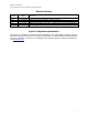
Iridium Satellite LLC 9522B L-Band Transceiver Product Information Guide Revision History Revision V0.1 V0.2 V0.3 V0.4 V1.0 Date 17 April 2008 22 May 2008 16 Jun 2008 30 June 2008 Comment First revision based on 9522A product information guide Updated mechanical drawings, mass and power. Updated Header and DC Power Input Specification Added 9522A adapter information.
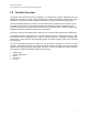
Iridium Satellite LLC 9522B L-Band Transceiver Product Information Guide 1.0 Product Overview The 9522B L-Band Transceiver (LBT) is designed to be integrated into a specific application with other hardware and software to produce a solution designed for a specific application or vertical market. Some examples of these solutions include a maritime voice telephony terminal or a vehicle tracking solution. The LBT functionally supports all of Iridium’s voice and data services.
Iridium Satellite LLC 9522B L-Band Transceiver Product Information Guide 2.0 Standards Compliance The 9522B is designed to comply with the standards for Radio Emissions Compliance, Electromagnetic Compatibility, and AC Safety in the United States, European Union and Canada. 2.1 FCC Compliance The 9522B is certified under 47 CFR Part 25 as FCC ID: Q639522B. It also complies with Part 15 of the FCC Regulations. Operation is subject to the condition that this device does not cause harmful interference.
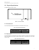
Iridium Satellite LLC 9522B L-Band Transceiver Product Information Guide 3.0 Physical Specifications The 9522B is depicted in Figure 1 below. Figure 1: Top View of 9522B 3.1 Environmental The environmental specifications of the 9522B LBT are summarized in Table 1 below. Table 1: Environmental Specifications Parameter Operating Temperature Range Operating Humidity Range Storage Temperature Range Storage Humidity Range Value -30ºC to + 70ºC 25 to 75% RH -40ºC to + 85ºC ≤ 93% RH 3.
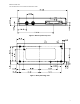
Iridium Satellite LLC 9522B L-Band Transceiver Product Information Guide Figure 2: Bottom (connector) View Figure 3: Back (mounting) View 7
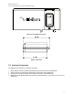
Iridium Satellite LLC 9522B L-Band Transceiver Product Information Guide Figure 4: Front (SIM access) View Figure 5: End View 3.
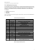
Iridium Satellite LLC 9522B L-Band Transceiver Product Information Guide 3.3.1 Multi-Interface Connector The multi-interface connector is a standard 26-pin 0.1” pitch short latch IDC header with pins in two rows of 13. Connection to this is made using a 26-way IDC without strain relief (such as AVX/Kyocera 00 8290 026 000 0X 1 or Harting 09 18 526 7803). To support legacy applications, a cable is available that converts its pin-out to a DB25 connector with the same pin-out as the 9522A.
Iridium Satellite LLC 9522B L-Band Transceiver Product Information Guide Contact 1 2 3 4 5 6 7 8 9 10 11 12 13 14 15 16 17 18 19 20 21 22 23 24 25 Signal EXT_ON_OFF EXT_11HZ EXT_GND EXT_PWR SPKR_AUD DA_TX DF_RI DF_RTS DF_S_TX DF_DCD DA_FS DA_CLK DF_S_RX 0V MIC_AUD EXT_PWR EXT_GND DPL_TX DF_DTR DPL_RX DF_DSR DF_CTS 0V DA_RX 0V Description External connection for On / Off key input to LBT 90ms “frame sync” signal (used in testing) Power Ground input to LBT Power input to LBT Speaker audio output from LBT P
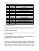
Iridium Satellite LLC 9522B L-Band Transceiver Product Information Guide Textron Camcar® Taptite® II Thread-Rolling Fastener with a 15IP Torx Plus® pan head is available in lengths of 1/4, 5/16, 3/8, 1/2, 5/8, 3/4, and 1 inch as part number 3BE-P814-00, 3BE-P8123-00, 3BEP815-00, 3BE-P816-00, 3BE-P8124-00, 3BE-P817-00, and 3BE-P818-00 respectively. A 10IP Torx Plus® flat head version is also available in a single length of 1/2 inch as part number 3BE-P801-00.
Iridium Satellite LLC 9522B L-Band Transceiver Product Information Guide 4.0 Electrical Interfaces The subsections to follow contain interface information for the electrical interfaces of the 9522B LBT. 4.1 DC Power Interface 4.1.1 DC Power Interface Signal Descriptions The DC power interface is comprised of the DC power inputs and a control signal as summarized in Table 5 below. The EXT_PWR and GND inputs are used to supply DC power to the 9522B LBT.
Iridium Satellite LLC 9522B L-Band Transceiver Product Information Guide 4.3 RS232 Data Interface 4.3.1 RS232 Data Signal Descriptions The RS232 data interface is comprised of eight standard RS232 data, control, and status signals plus a ground level signal reference. This interface allows a connected Data Terminal Equipment (DTE) to utilize the 9522B LBT’s modem functionality via AT command control.
Iridium Satellite LLC 9522B L-Band Transceiver Product Information Guide 4.6 RF Interface 4.6.1 R F Interface Specifications The RF interface requirements for the 9522B LBT are summarized in Table 7 below. Table 7: General RF Parameters Parameter Value Frequency Range 1616 MHz to 1626.5 MHz Duplexing Method TDD (Time Domain Duplex) Oscillator Stability ± 1.5 ppm Input/Output Impedance 50Ω Multiplexing Method TDMA/FDMA 4.6.
Iridium Satellite LLC 9522B L-Band Transceiver Product Information Guide 5.0 Instructions for the safe Installation and use of the 9522B LBT The 9522B LBT is intended for integration into a finished product. The integrator of the 9522B LBT is required to connect a power supply, antenna, and user interface to the 9522B LBT. To ensure that the 9522B LBT is correctly installed the following general instructions (sub-section 5.1) are provided for the installer.
Iridium Satellite LLC 9522B L-Band Transceiver Product Information Guide 7.0 Installation of the 9522B in place of a 9522A The 9522B is designed to replace the 9522A with the assistance of an optional adapter plate and cables. An adapter plate is mounted onto the 9522B and provides mounting points similar to those of the 9522A. The antenna cable adapter provides a cable-mounted TNC connector similar to the 9522A.
Iridium Satellite LLC 9522B L-Band Transceiver Product Information Guide Figure 8: Front (SIM access) View Figure 9: End View 7.2 Power Supply With the adapter cables in use, the requirements for the signals to and from the 9522B are as given in section 3.3. Note that it is important to ensure that the power supply voltage measured at the 9522B multi-way connector does not fall below 4.0v.