
User Manual
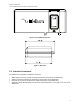
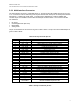
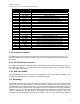


Table Of Contents
- 1.0 Product Overview
- 2.0 Standards Compliance
- 3.0 Physical Specifications
- 4.0 Electrical Interfaces
- 5.0 Instructions for the safe Installation and use of the 9522B LBT
- 6.0 Modem Commands and Configuration
- 7.0 Installation of the 9522B in place of a 9522A

Iridium Satellite LLC
9522B L-Band Transceiver Product Information Guide
4.0 Electrical Interfaces
The subsections to follow contain interface information for the electrical interfaces of the 9522B LBT.
4.1 DC Power Interface
4.1.1 DC Power Interface Signal Descriptions
The DC power interface is comprised of the DC power inputs and a control signal as summarized in Table
5
below. The EXT_PWR and GND inputs are used to supply DC power to the 9522B LBT. The
EXT_ON_OFF control input is pulled to a GND level to toggle the 9522B LBT on and off. Note that both
pairs of pins should be connected for EXT PWR and EXT GND.
Table 5: Control/Audio Interface Signal Descriptions
Signal Name Signal Description
EXT_PWR (pin 6 and 7) External power input
EXT_GND (pin 5 and 8) External power GND input
EXT_ON_OFF (pin 1) Power on/off control input
4.1.2 DC Power Input Specifications
The DC power requirements for the 9522B LBT are summarized in Table 5 below. Note that these
requirements apply to DC power measured at the 9522B LBT multi-interface connector input.
Table 5: DC Power Input Specifications
Parameter Value
Main Input Voltage Range +4.0 VDC to +32 VDC
Main Input Voltage - Nominal 5VDC, 12VDC or 24VDC
Main Input Voltage – Ripple 40 mV peak to peak
Consumption at +5 VDC
Value
Input Standby Current (average) 250mA
Max current during call 2.5A
Typical current during call (see note) 800mA
Power Average – Voice/Data Call (see note) 4W
Note: The average power consumption depends on the view of the satellite constellation from the
antenna.
4.2 Control/Digital Audio (DPL bus) Interface
4.2.1 Control/Digital Audio Interface Signal Descriptions
The control/digital audio interface enables peripherals such as handsets and SIM card readers to be
interfaced to the 9522B LBT. The interface utilizes an Iridium Proprietary communication bus not detailed
in this fact sheet. Details can be made available after appropriate Non-Disclosure and/or License
Agreements are executed.
12