
User Manual
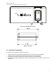
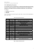
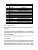


Table Of Contents
- 1.0 Product Overview
- 2.0 Standards Compliance
- 3.0 Physical Specifications
- 4.0 Electrical Interfaces
- 5.0 Instructions for the safe Installation and use of the 9522B LBT
- 6.0 Modem Commands and Configuration
- 7.0 Installation of the 9522B in place of a 9522A

Iridium Satellite LLC
9522B L-Band Transceiver Product Information Guide
4.3 RS232 Data Interface
4.3.1 RS232 Data Signal Descriptions
The RS232 data interface is comprised of eight standard RS232 data, control, and status signals plus a
ground level signal reference. This interface allows a connected Data Terminal Equipment (DTE) to utilize
the 9522B LBT’s modem functionality via AT command control. A 3-wire RS232 Data minimal interface
may also be implemented however the 9 wire interface offers better control and is the recommended
implementation.
4.3.2 Autobaud
Autobaud is enabled by default. Autobaud will occur on the following characters ‘a’, ‘A’, or CR (carriage
return). Autobaud will also occur on the escape sequence character, provided this is an odd number
character. Normally this is set to ‘+’ in register S2. See the AT Command Reference for details.
4.4 Analog Audio Interface
4.4.1 Analog Audio Interface Signal Descriptions
The analog audio interface is comprised of the analog audio input and output signals referenced to the 0V
signal ground as summarized in Table 6 below.
Table 6: Analog Audio Interface Signal Descriptions
Signal Name Signal Description
MIC_AUD (pin 4) Analogue audio input to LBT
SPKR_AUD (pin 9)
Analogue audio output from
LBT
0V (pins 2, 20, 24) Signal ground
4.5 SIM Interface
An integrated SIM chip reader is provided on the 9522B LBT. An external SIM card reader may also be
interfaced as a peripheral to the 9522B LBT via the DPL bus (control/audio interface). A SIM card in the
external reader will take precedence over the SIM chip in the integrated connector when both are present.
13