
User's Manual


Iridium Satellite LLC
9601 SBD Transceiver Preliminary Product Developers Guide
V1.2 082905
Iridium Satellite LLC Proprietary & Confidential Information
Information contained herein is preliminary and subject to change without further notice
10
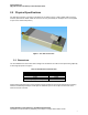
2.2.1 Mounting - Stackable Design
An example stackable design is shown in Figure 3.
Figure 3: 9601 Transceiver mounted to a unpopulated PCB.
The figures and tables below provides mechanical information design information for a suitable
‘stackable’ 9601 to developer PCB configuration
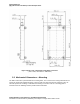
Figure 4: Assembly Item Number Identification.
Item Numbers in Figure 4 are described in Table 3. Not to scale. Dimensions in millimeters.
Table 3: Item Number Description for Figure 4
Item Type Description Quantity
1 Assembly 9601 Transceiver 1
2 Part M3 Shake-proof washer, zinc plated steel [4 supplied with item 1] 8
3 Part M3 x 20 Pan head screw, pozidrive, zinc plated steel [4 supplied with item 1] 4
4 Part M3 Threaded standoff, 6.0 A/F HEX x 12.00 mm 4
5 Part M3 x 8 Pan head screw, pozidrive, zinc plated steel 4
6 Assembly
Solution developer PCB fitted with Samtec connector ESQT-113-02-L-D-425.
[This item is the same item as Item 1 in Figure 5.]
1