
User's Guide


`
This document contains Iridium Satellite LLC Proprietary Information may which may not be used, reproduced, or
disclosed without written approval from Iridium Satellite LLC.
IR3142-ICD-006 Issue 1 v2.1 Page 12 of 16
4.4 Mounting Considerations
The Iridium Certus 9770 has six mounting holes with clearance for M3 screws that can be used
to secure the transceiver to a VAM product. The Iridium Certus 9770 should be assembled into a
VAM product by pushing the transceiver straight down onto a VAM product’s mating connector,
ensuring not to rotate or twist the transceiver.
The mechanical drawings in section 4.3 define a keep-out region. VAM product components
should not be placed inside this keep out area which has allowances for reasonable
manufacturing and assembly variations.
4.5 Grounding
Ground pins on the Iridium Certus 9770 digital connector are the intended return path for all return
currents. As such, although the Iridium Certus 9770’s metal enclosure is also electrically
connected to a ground, it is recommended that all high current ground returns only flow through
the ground pins on the digital connector.
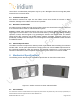
4.6 Thermal Management
The Iridium Certus 9770 has an aluminum die cast enclosure which provides a passive thermal
heat sink path that is designed to conduct, connect and/or radiate heat from its bottom surface to
a VAM product. Figure 4.6-1 illustrates the location on the Iridium Certus 9770’s power amplifier
where the dominate heat is generated. At a minimum, it is recommended that heat sinks on a
VAM product contact the Iridium Certus 9770 at this location. Depending on a VAM product design
and use case scenarios, larger heat sink contact zones may be required.
Figure 4.6-1: Primary Heat Source location
A VAM product is responsible for dissipating enough heat from the Iridium Certus 9770 into the