
User Manual
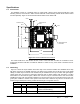

Table Of Contents

_____________________________________________________________________________________________________
User Guide, iCLASS OEM050 Drawing No: 3131-901
Rev 1 Sheet: - 4 -
Specifications
1.3 Form Factor
The OEM050 consists of 3 separate PCB’s; A reader PCB, a 80mm square antenna PCB with a 50Ω
matching network, and a 34mm x 48mm antenna PCB with a 50Ω matching network. Both antenna PCB’s
are sold separately. Figure 2.1 shows the dimensional outline of the reader PCB.
Connector P1
Pin 1
0.050
Connector P2
Pin 1
0.100
1.100
1.200
0.250
0.100 TYP
1.100
1.000
0.100
MCX Style Coax
Connector
Figure 2.1: Reader PCB Dimensional Outline
The reader PCB has 4 slots located at each corner of the PCB that are sized for a #2-56unc screw.
Component placement will allow a maximum diameter of 0.200” for any screw head or standoff used for
installation.
1.4 Interfacing
Figure 2.1 shows two 6-pin headers and a MCX style coax connector installed. The OEM050 will not ship
with these connectors for flexibility purposes. The holes for the headers are &0.035 and may accept pigtail
cabling or header style connectors. The headers may be installed from the top or bottom and right angle or
vertical styles may be used but component placement will not allow headers with shrouding or locking
mechanisms. For the antenna signal, a MCX coax connector may be mounted from the side of the board,
straddling the edge, with the signal pin soldered to a surface mount pad on the top side and two of the four
ground pins soldered to surface mount pads on the bottom side. Antennas may also be connected to the
module using a twisted pair of wires, provided the wire length is not greater than 3.0”.
I/O Functionality
Connector Pin # Pin Name Function
P1 1 Exc Supply Separate supply for the antenna exciter.
Includes on-board filtering.
P1 2 Exc Return Return for the exciter supply.