IRIS DC1100/DC1100E Business Class Cable Modem Termination System Installation and Operational Guide Coaxial Networks, Inc. P/N DC1100-UG Revision: 4.
This page intentionally left blank Coaxial Networks, Inc.
Table of contents Software License.......................................................................................... 7 Limited Warranty ........................................................................................ 8 Introduction................................................................................................... 11 Key Benefits .............................................................................................. 11 Installation Requirements..........................
vi Syntax................................................................................................. 55 Miscellaneous 1 ...................................................................................... 57 ex Commands......................................................................................... 58 ex syntax................................................................................................. 58 The vi environment variables......................................................
Table of Figures Figure 1 IRIS Rear Panel .................................................................................................. 13 Figure 2 IRIS Front Panel ................................................................................................. 14 Figure 3 Attaching mounting braces for flat wall mount.................................................. 15 Figure 4 Flat Wall Mount .................................................................................................
This page intentionally left blank Coaxial Networks, Inc.
Copyright © 2001-2005, Coaxial Networks, Inc. All rights reserved. Printed in USA Product names mentioned herein may be trademarks and/or registered trademarks of their respective companies. Coaxial Networks, Inc. shall not be liable for technical or editorial errors or omissions in this document; nor for incidental or consequential damages resulting from the furnishing, performance, or use of this material.
ROM or floppy disk), down loaded from CNI or delivered through customer support. Any such additional software shall be considered "Soft-ware" for all purposes under this License. 5. Export Law Assurances. You acknowledge that the Software may be subject to export control laws and regulations of the U.S.A. You confirm that you will not export or re-export the Software to any countries that are subject to export restrictions. 6. No Other Rights Granted.
C. Returned Products will be tested upon receipt by CNI. Products that pass all functional tests will be returned to the end user. D. CNI will return the repaired or replacement Product to the end user at the address provided by the end user at CNI Network's expense. For Products shipped within the United States of America, CNI will use reasonable efforts to ensure delivery within five (5) business days from the date received by CNI. Expedited service is available at additional cost to the end user. E.
agreement between CNI and the end user, and supersedes all prior and contemporaneous representation, agreements or understandings, oral or written. This Software License and Limited Warranty may not be changed or amended except by a written instrument executed by a duly authorized officer of CNI.
Introduction Coaxial Networks provides an integrated solution to the hospitality businesses, apartment complexes and broadband service providers for deploying Internet services. The solution is geared towards cutting down challenges such as cost and rack space faced by the hotel operators. IRIS DC1100 is a very compact and cost effective solution. Using IRIS, Network or System Integrators can deploy blazing fast Internet over existing coax and cable TV infrastructure.
Installation Requirements To successfully install and configure the IRIS DC1100, you will need the following: PC Workstation Requirement Ethernet network Interface TCP/IP network protocol installed Terminal emulation or Telnet software for configuring IRIS via your PC’s serial port or network before placing it into service on a network. HyperTerminal is such software included in Windows operating system.
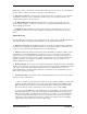
IRIS Rear Panel Connections The diagram below illustrates the relevant rear panel ports and connections on the IRIS. Autoswitching 110/230V Power Supply Coax Transmit Port 100 Mbps Ethernet Uplink Port Coax Receive Port UPLINK RX2 RX1 TX CONSOLE Power Supply Cooling Fan Male DB9 Serial Console Port PWR ACT RF ON Air Ventilation Figure 1 IRIS Rear Panel IRIS Rear Panel consists of the following connectors and labels 1. 2. 3. 4. 5. 6. 7.
IRIS Front Panel The diagram below illustrates the front panel controls of the IRIS. SYSTEM FANS, (DON'T BLOCK WHILE MOUNTING) IRIS Cable Modem Termination System RACK MOUNTING BRACES (REMOVALBLE) Figure 2 IRIS Front Panel The front panel has no indicators or controls. 1. Removable rack mounting braces for 19” rack mounting. 2.
Mounting Flat on Wall To mount the IRIS chassis for flat wall mount use the supplied rack mounting braces and attach them to the holes in the middle of chassis using the same screws. Holes for Rear Mounting IR I SF Holes for Flat wall Mounting ron t Holes for Front Mounting Figure 3 Attaching mounting braces for flat wall mount You will need appropriate screws to secure the chassis to the wall. If you have a dry wall, recommended screws are hollow wall anchor screws.
air to flow in and out of the system. Sufficient airflow will guarantee peek performance and longevity of the IRIS system. Coaxial Networks, Inc.
Setup Connecting Your IRIS DC1100 1. Place your IRIS DC1100 in a location where it will be well ventilated. Do not stack it with other devices or place it on carpet. 2. Connect your WAN equipment Ethernet port with CAT5 cross over cable to IRIS DC1100 Ethernet Port. If connecting to a hub or switch use a CAT5 straight through cable. 3. For coaxial connections determine the model number of the IRIS unit. The following models come with integrated fully agile 256 QAM DOCSIS Upconverter.
Coaxial Cable Specifications The coaxial cable used to connect the IRIS DC1100 series universal broadband routers at the Headend should be very high-quality cable. Coaxial recommends that you use a Headend-grade coaxial cable or a quad-shield coaxial cable with a minimum of 60% + 40% braid and double foil insulation to connect the cable modem cards to the HFC network. The center conductor must be straight and extend 1/8 inch (3.
Connections Cable Network Diagram IRIS Connections with Integrated Upconverter IRIS model numbers DC1100 and DC1100C come with an integrated upconverter. The following diagram illustrates the connections.
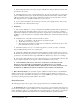
UPLINK Diplexer RX1 TX CONSOLE PWR ACT RF ON IRIS Rear Panel RF OUT IF IN Upconverter Rear Panel Diplexer TO DISTRIBUTION Figure 6 Connections with an external Upconverter IRIS Uplink Connection IRIS Uplink port is a 10/100 Ethernet port, which has to be connected to back office network switch or the uplink device such as satellite or DSL modem. When connecting to a switch a straight Cat5 Ethernet cable will be required.
Configuration Configuring IRIS All IRIS systems can operate in Bridge or Routing mode with NAT enabled on the cable interface. At the time of shipping the system IRIS is configured to work in the routing mode with NAT enabled on the cable interface. When NAT is enabled IRIS routes packets from its cable interface to the Ethernet interface and vice-versa. The diagram below represents the IP network topology with such configuration.
Connecting using Web Interface Start your Internet browser and point it to http://192.168.21.1:2380. You will be prompted by the “IRIS Admin” login window. Please enter the User name and Password to authenticate. All IRIS systems ship with default user name “iris” and password “123456”. IRIS Setup home page will appear in your browser as shown in Figure 9. Figure 8 Web Login Figure 9 Setup home page Coaxial Networks, Inc.
The Web interface can be used to configure the following parameters 1. 2. 3. 4. 5. 6. 7. 8. TCP/IP parameters IRIS Operational mode Web login password Cable modem subscription Cable modem tftp configuration file generation for QOS Downstream channel, QAM mode and Output power level Upstream frequency for each channel Report cable modem status Configuring TCP/IP parameters To configure TCP/IP parameter for IRIS or to set its operational mode click on the “Network” on the left hand side navigational menu.
Configuring IRIS in Router mode All IRIS systems ship with operational mode set to “router”. In router mode the cable interface is configured with a private interface and all cabled modems and CPEs attached to the cable modems are automatically assigned IP addresses from this private addressing scheme. You will need to configure the “Uplink Interface” or the Ethernet Interface with the ISP provided configuration parameters.
Configuring IRIS in Bridge mode To configure IRIS in “bridge” mode select “Network” from the navigation menu bar. If you configure IRIS in bridge mode, you will need to use an external provisioning server that can provide all the required server functionality which includes DHCP server, TFTP server and TOD server. Figure 12 Network Setup You will also need to configure you provisioning server so that it can allocate IP addresses to CPE devices that are behind the cable modems.
Figure 13 Bridge mode setup This will change the IRIS Setup screen so that the system can be configured in the bridge mode. In bridge mode IRIS only has one interface, which is the “cable” interface. IRIS then forward all traffic from the HFC side to the Ethernet side. If you are planning to use the DHCP server available on IRIS do not change “Cable CM Interface” address.
Figure 14 Bridge Mode Configuration Coaxial Networks, Inc.
Configuring Downstream RF Settings DOCSIS protocol utilizes an available channel to send downstream signal for data communications. Depending upon the frequency plan NTSC or PAL, IRIS automatically provides you the channel number and the center frequency in a drop down menu. Figure 15 Downstream RF Settings Using the “Center frequency with channel number” select the channel that you wish to use to send downstream signal. This channel should not be used to send any video signal.
Configuring Upstream RF Settings DOCSIS protocol utilizes a separate upstream frequency to provide upstream data communication back from the cable modem. Your cable plant has to be two way ready or return passing to provide high speed data communication over cable. The North American plan uses up to a 3.2MHz wide channel in the 5-42MHz frequency range. The European plan uses up to a 3.2 MHz wide channel in the 5-65MHz frequency range.
Creating Class of Service Profiles DOCSIS based data networks allow each cable modem to be associated to a class of service. This class of service configuration is downloaded by the cable modem during registration process using TFTP protocol. IRIS provides a user interface using which you can enter different values for a cable modem configuration file and then save these settings to class of service.
In the “US Priority” specify the priority that you wish to assign traffic coming from this cable modem in the upstream direction. IRIS supports 1 to 7 upstream priority classifications, 1 being the highest. In the “Guaranteed US Rate” specify upstream data rate which you wish to guarantee for each cable modem. For example for voice traffic a guaranteed upstream rate of 64000 is recommended.
Controlling Cable Modem Access IRIS can allow all or selectively allow cable modems connected to your cable network to gain access to the Internet. ) By default IRIS is configured such that all modems that are connected on your cable plant can gain access to the Internet. To enable conditional access to certain we need to enable conditional access and then add the MAC addresses of the cable modems. Once it has been done only cable modems with these MAC addresses can register with IRIS.
the location of each cable modem and also associate the cable modem to one of the class of service profiles you have created. If you have not created any class of service profiles, create a class of service using the “CM configuration” option. A cable modem that had yet not been connected to the cable network will not show up in the “unsubscribed modems” list.
You will need to save the “subscribed modems” list so that the same is available after a system restart. Press the “Save” button to save or update the “subscribed modems” list to the flash memory of IRIS. Coaxial Networks, Inc.
IRIS CLI interface using Telnet IRIS also provides a CLI interface for certain advanced configuration and diagnostics. You will need a PC to connect using telnet. You should be able to connect to IRIS from the HFC side if you have successfully been able to bring up a cable modem. The easiest way to connect to IRIS is from the Ethernet interface of IRIS.
Using a serial (RS232) 9 pin null modem cable connect your PC’s serial port to the serial console port of IRIS. Now you can use tools such as “HyperTerminal” in Windows to connect to IRIS. The settings for the serial console port of IRIS are Baud Rate: 57600 Data Bits: 8 Parity: None Stop Bits: 1 Flow Control: None After successfully connecting to the console port you should see the IRIS “login” prompt. Logging In At the login prompt, type the username as “iris” and hit enter.
psid............................ preg............................ pcpe............................ config_cm ...... (q)uit ......................... system ......................... reboot ......................... shutdown ....................... !............................... tty............................. passwd.......................... upcon .................... setupl ......................... setif ...... showif [if] .................... dhcp ......
------------------------------------------------------------------------------00:0b:00:02:01:0a 00:0b:06:9f:a7:fe 00:10:5a:d0:1d:cd 00:10:95:1b:e1:c5 00:10:b5:3e:56:a2 00:30:eb:bc:0c:a5 00:90:83:8c:58:23 00:e0:ca:00:c1:9c ff:ff:ff:ff:ff:ff 0x0002 0x0002 0x0001 0x0001 0x0002 0x0004 0x0003 0x0005 0x16383 Total:(9) Figure 23 List of SID and their MAC addresses “pcpe” command The “pcpe” command displays you a list of MAC addresses of cable modems that have communicated to IRIS, their SID (service identifier
The “count” command displays the number of Interrupts, Packets received, Packets Transmitted and Errors on the cable interface of IRIS. “rcount” command Resets the values of the above mentioned counters. “ver” command Displays the version of IRIS and IRIS CLI. “reboot” command Restarts the system. “shutdown” command Shuts down the system, so that it can be powered off safely. “system” command Takes you to the QNX system prompt from the IRIS CLI.
“upcon” command Using the “upcon” command you can program and check status of the integrated upconverter in the IRIS DC1100 and IRIS DC1100C. Upcon FL Load upconverter with the desired frequency, output is muted and then unmuted. For example to set the downstream frequency to 369MHz, at the “IRIS>” prompt type upcon fl 369000000 Consult chapter on “Channel Frequency Chart” to find center frequency of a TV channel that you wish to use.
Loads the RF Attenuator with desired value. Upcon RAS Sets high and low values for RF ALC. Upcon RAD Disable RF ALC. Upcon RAE Enable RF ALC. This is the default setting. Upcon RLS Sets the RF power limit. Upcon RPS Sets the RF Power. Upcon RTD Disable the RF Threshold. Upcon RTE Enable the RF Threshold. Upcon RTS Sets the desired value for the RF Threshold.
This page intentionally left blank Coaxial Networks, Inc.
Application Notes Network traffic between cable clients By default IRIS does not allow traffic between CPEs behind cable modems on the same IRIS. To enable this you have to turn the “NetLoopbackMode” setting in iris.txt file to “1”. Edit the “iris.txt” file from the system prompt and then change the above seeting to NetLoopbackMode = 1 Save the file and restart IRIS. Allowing PPPoE traffic across IRIS By default IRIS is configured to forward Ethernet packets of IP protocol type only.
To create a BIMAP you will need to know the MAC address of the CPE. To obtain this you can Telnet to IRIS and issue the "pcpe" command find the cable modem that the end user has, attached you will see his CPE Mac address. Assigning a reserved IP address to the CPE. Edit the /etc/dhcpd.conf file and add a "host" entry for the MAC address of the CPE with a Reserved IP address in the "#CPE Network" subnet host user1 { hardware ethernet 00:12:17:4C:9b:21; fixed-address 10.71.0.
Channel Frequency Chart NTSC Channel Frequency Chart in MHz (DOCSIS) Channel Number Bandwidth Coaxial Networks, Inc. Center Frequency FM 88.0 - 108.0 A-5 - 95 90.0 - 96.0 93.00 A-4 - 96 96.0 - 102.0 99.00 A-3 - 97 102.0 - 108.0 105.00 A-2 - 98 108.0 - 114.0 111.00 A-1 - 99 114.0 - 120.0 117.00 A - 14 120.0 - 126.0 123.00 B - 15 126.0 - 132.0 129.00 C - 16 132.0 - 138.0 135.00 D - 17 138.0 - 144.0 141.00 E - 18 144.0 - 150.0 147.00 F - 19 150.0 - 156.0 153.
Coaxial Networks, Inc. V - 35 288.0 - 294.0 291.00 W - 36 294.0 - 300.0 297.00 AA - 37 300.0 - 306.0 303.00 BB - 38 306.0 - 312.0 309.00 CC - 39 312.0 - 318.0 315.00 DD - 40 318.0 - 324.0 321.00 EE - 41 324.0 - 330.0 327.00 FF - 42 330.0 - 336.0 333.00 GG - 43 336.0 - 342.0 339.00 HH - 44 342.0 - 348.0 345.00 II - 45 348.0 - 354.0 351.00 JJ - 46 354.0 - 360.0 357.00 KK - 47 360.0 - 366.0 363.00 LL - 48 366.0 - 372.0 369.00 MM - 49 372.0 - 378.0 375.
Coaxial Networks, Inc. NNN - 76 534.0 - 540.0 537.00 OOO - 77 540.0 - 546.0 543.00 PPP - 78 546.0 - 552.0 549.00 QQQ - 79 552.0 - 558.0 555.00 RRR - 80 558.0 - 564.0 561.00 SSS - 81 564.0 - 570.0 567.00 TTT - 82 570.0 - 576.0 573.00 UUU - 83 576.0 - 582.0 579.00 VVV - 84 582.0 - 588.0 585.00 WWW - 85 588.0 - 594.0 591.00 XXX 86 594.0 - 600.0 597.00 YYY - 87 600.0 - 606.0 603.00 ZZZ - 88 606.0 - 612.0 609.00 89 - 89 612.0 - 618.0 615.00 90 - 90 618.0 - 624.0 621.
Coaxial Networks, Inc. 122 - 122 780.0 - 786.0 783.00 123 - 123 786.0 - 792.0 789.00 124 - 124 792.0 - 798.0 795.00 125 - 125 798.0 - 804.0 801.00 126 - 126 804.0 - 810.0 807.00 127 - 127 810.0 - 816.0 813.00 128 - 128 816.0 - 822.0 819.00 129 - 129 822.0 - 828.0 825.00 130 - 130 828.0 - 834.0 831.00 131 - 131 834.0 - 840.0 837.00 132 - 132 840.0 - 846.0 843.00 133 - 133 846.0 - 852.0 847.
PAL Frequency Allocation (EuroDOCSIS) System L France System K1 France Overseas System I RSA System I Ireland System D OIRT System D PRC Center Frequency 6 4 4 RVI ID 7 1 5 5 RVII IE 8 2 6 6 RVIII IF 9 3 7 7 RIX IG 10 4 8 8 RX IH 11 5 9 9 RXI U 12 6 10 RXII 13 11 13 171 MHz 178 MHz 179 MHz 179.5 MHz 186 MHz 187 MHz 187.75 MHz 194 MHz 195 MHz 195.75 MHz 202 MHz 203 MHz 203.75 MHz 210 MHz 211 MHz 211.75 MHz 218 MHz 219 MHz 219.
System G - Hyperband S 21 S 22 S 23 S 24 S 25 S 26 S 27 S 28 S 29 S 30 S 31 S 32 S 33 S 34 S 35 S 36 S 37 S 38 S 39 S 40 S 41 Channel Center Frequency 306 MHz 314 MHz 322 MHz 330 MHz 338 MHz 346 MHz 3564 MHz 362 MHz 370 MHz 378 MHz 386 MHz 394 MHz 402 MHz 410 MHz 418 MHz 426 MHz 434 MHz 442 MHz 450 MHz 458 MHz 466 MHz Table 2 Channel Center Frequencies for System G – Hyperband Coaxial Networks, Inc.
System G UHF Europe Channel 21 Channel 22 Channel 23 Channel 24 Channel 25 Channel 26 Channel 27 Channel 28 Channel 29 Channel 30 Channel 31 Channel 32 Channel 33 Channel 34 Channel 35 Channel 36 Channel 37 Channel 38 Channel 39 Channel 40 Channel 41 Channel 42 Channel 43 Channel 44 Channel 45 Channel 46 Channel 47 Channel 48 Channel 49 Channel 50 Channel 51 Channel 52 Channel 53 Channel 54 Channel 55 Channel 56 Channel 57 Channel 58 Channel 59 Channel 60 Channel 61 Channel 62 Channel 63 Channel 64 Channel
Channel 57 Channel 58 Channel 59 Channel 60 Channel 61 Channel 62 866 MHz 874 MHz 882 MHz 890 MHz 898 MHz 906 MHz Table 3 Channel Center Frequencies for System G and D Coaxial Networks, Inc.
Regulatory Compliance Agency Standards The IRIS system complies with the following standards and agency requirements: • • • • Compliance Marking: CE, FCC Safety : EN60950 EMC Emissions: EN55022A:CISPR:1993 EMC Immunity: EN55024 – 1998 Standard; EN61000-4-2; EN61000-4-3, EN61000-4-4; EN61000-4-5; EN61000-4-6; EN61000-4-8; EN61000-4-11:1994; EN61000-3-2; EN61000-3-3 Coaxial Networks, Inc.
Specifications IRIS DC1100 Physical: • Form Factor 1U “Pizza Box” • Height 1.75 in / 4.45 cm • Width 17.5 in / 44.4 cm • Depth 12 in / 30.5 cm • Weight 10 lbs / 4.
VI (Visual) Editor The vi is a text editor. It is small, powerful, and standard on most UNIX systems. The vi often frustrates new users with a unique distinction between its two modes: Command Mode and Insert/Overtype Mode. This distinction, although difficult to become accustomed to for many users, provides great power and ability to the editor. Insert/Overtype Mode is designed for inserting text only. All text manipulations and cursor moving should be done from with in Command Mode.
execute operator n times on m objects. If n and/or m are omitted, they default to 1. Operators which take objects are(if the operator is pressed twice then the object is the current line) c -- Change d -- Deletion "cy -- Yank, if "c is omitted, uses general buffer. < -- shift lines left by shiftwidth variable > -- shift lines right by shiftwidth variable !cmd -- filter trough cmd The operators <, >, and ! are line based so the set of objects is diminished greatly.
Fc -- backward until and including next appearance of c on current line ; -- repeat last f, F, t, or T , -- repeat last f, F, t, or T in reverse } -- forward until end of paragraph { -- backward until end of paragraph ) -- forward until end of sentence ( -- backward until end of sentence ]] -- forward until end of section [[ -- backward until end of section nH -- n lines before first line on screen; n defaults to 0 nL -- n lines before last line on screen; n def
-- execute last ex-style substitution .
refer to ex manual page for more commands The vi environment variables set You can customize your environment with this command by typing set var=value, this will set the specified var to value for a scalar variable. For Boolean variables, use set var to set and set novar to unset. You can see which variables are set by just typing the set by itsself. You can see a list of all variables by typing set all. Some environment variables are specific to the ex editor and some are specific to the vi editor.
:n -- start editing next file in list :rew -- rewind file list, start editing 1st file on argument list again Q -- quit vi and enter ex :pre -- Preserve file.