
Installation Manual

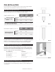


ADJUSTABLE SWIVEL
SURFACE MOUNT INSTALLATION
Models | AE46, ANE-46, AE-42, ANE-42, UD-42
STEP ONE: Locate Stud & Pre-Drill Holes
STEP TWO: Install Unit on Wall
STEP THREE: Apply Trim
STEP FOUR: Anchor Swivel
*** PLEASE NOTE: Under no circumstances should the ironing board and/or
the support mechanism be removed from the cabinet during installation.
Locate and mark stud on wall. Cut two 2 x 4 braces (not provided) to the
desired mounting height to use for bracing the unit for installation.
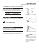
Using 3/16” drill bit, pre-drill hole into the center of the top cleat of cabinet
(FIG 3.1)
With 2 x 4 braces in place for support (FIG 3.2), place unit on wall, centering
with desired stud.
Mark the location for mounting by placing the drill bit through the pre-drilled
hole in cabinet. Dimple the wall by lightly pushing the drill bit into the dry
wall. Set unit aside, then adjust location if not centered on stud, and pre-drill
hole in wall for mounting.
Partially insert one #14 x 4” screw into the pre-drilled cabinet hole. Then,
using 2 x 4 braces, place unit back on the wall (FIG 3.2) and fully insert screw
through cabinet cleat and into stud (FIG 3.1). Remove braces. Plum and level
unit.
Using 3/16” drill bit, pre-drill hole through bottom cleat of cabinet into stud.
Insert remaining #14 x 4” screw through cleat into stud to fully anchor the
unit.
Apply trim [not provided] to sides of cabinet to flush the side wall with the
cabinet trim (FIG 3.3) to create a sleek look.
Note: May use custom trim or purchase Surface Mount Trim from Iron-A-Way
directly. Please call 1-800-536-9495 for more information.
Locate swivel brackets near bottom of cabinet and remove top screws only
from both sides, and replace with #14 x 1” screws [not provided] (FIG 3.4). This
will provide anchoring for your swivel.
Note: #14 x 1” screws available upon request. Please call us at 1-800-536-9495.
MODELS AE-46, AE-42, & UD-42:
PLEASE REFER TO ELECTRICAL INSTRUCTION
ON PG. 7 BEFORE PROCEEDING.
INSTALLATION COMPLETE!
FIG. 3.2
FIG. 3.1
FIG. 3.3
FIG. 3.4
ADJUSTABLE SWIVEL MODELS | PG. 4