
Instruction Manual


Surface Mounting
When surface mounting recessed units, it is recommended a trim kit be installed.
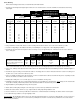
1. Determine desired ironing board height using the chart below. Care should be taken to ensure the unit will be mounted at the desired ironing
board height.
A-42
A-46 E-342 with Optional Swivel
with NE-342 with Optional Swivel E-342
A-46 Optional Swivel NE-242 with Optional Swivel * NE-342 NE-242
Ironing Ironing Ironing Ironing Ironing
Board Height Board Height Board Height Board Height Board Height
Opening Height Regular Adjusted Regular Adjusted Regular Adjusted Regular Regular
Above Floor Position Position Position Position Position Position Position Position
30" 37" 35"
29" 36" 34"
28" 35" 39" 35" 33"
27" 34" 38" 34" 32"
26" 33" 37" 33" 31"
25" 32" 36"
24" 37" 41" 31" 35"
23" 37" 33" 36" 40"
22" 36" 32" 35" 39"
21" 35" 31" 34" 38"
20" 34" 30" 33" 37"
19" 33" 29"
* Note: NE-242 with Swivel Option does not adjust in vertical height.
2. Using a stud finder, locate the wall stud to be used for mounting. Stud should be located as close to the center of cabinet as possible.
3. Locate the existing wiring or other utilities in the wall to prevent drilling into or severing a wire or other utility during installation.
4. Determine the desired location has adequate clearance for ironing. Door opens approximately 180°. Allow at least 16" from side of cabinet for
door to swing open.
A-42
A-46 with E-342 E-342 with Optional Swivel NE-242 with
Optional NE-342 NE-342 with Optional Swivel Optional
A-46 Swivel NE-242 Swivel
Distance from Wall to Tip of Ironing Board 49" 54 1/4" 45" 51" 44" 47"
Swivel Clearance from Side of Cabinet N/A 16 7/8" N/A 14 5/8" N/A 14 5/8"
Distance from Wall in Full Swivel Position N/A 36 3/16" N/A 36 13/16" N/A 32 5/8"
Standing Area Clearance ** 24" 24" 24" 24" 24" 24"
** The recommended distance from the side of the ironing board where the user will typically stand to ensure adequate space for ironing.
5. Using a 3/16", drill bit pre-drill a pilot hole into the wall stud where the cabinet will be attached to the wall taking care that the installation height is as
desired.
6. Determine the proper mounting screw location inside cabinet so mounting position is located on wall stud as intended. Location for mounting screw
should be as close to the center of the cabinet as possible.
7. Using a 1/4" drill bit, pre-drill hole in the upper and lower cross braces located inside the cabinet as determined in the previous step taking care that
the holes in both braces are drilled to same measurement.
8. Partially start mounting #14 x 3 1/2" screw into upper cross brace for installation of ironing center.
9.
If
i
nsta
lli
ng an e
l
ectr
i
ca
l
mo
d
e
l
, p
l
ease rev
i
ew
El
ectr
i
ca
l
I
nstruct
i
ons now.
If
i
nsta
lli
ng a non-e
l
ectr
i
ca
l
mo
d
e
l
,
d
o not
i
nsta
ll
your own e
l
ectr
i
ca
l
out
l
et
inside cabinet. Warranty voided if independent electrical outlet installed within non-electrical ironing center cabinet.
10. Begin installation by carefully lifting the ironing center into position.
11. Attach cabinet to wall by fully inserting the screw in the upper cross brace into the pre-drilled hole in the wall stud.
12. Plumb and level the cabinet. Shim if necessary. Tighten cabinet to wall by fully turning installation screw.
13. Insert second #14 x 3 1/2" screw into pre-drilled hole in bottom brace of cabinet and attach to wall making sure cabinet remains level and square.
14. Decorative trim may be added to cover any irregularity on wall.
R
ecommen
d
at
i
on:
O
n a
ll
a
dj
usta
bl
e sw
i
ve
l
mo
d
e
l
s,
l
ocate s
id
e
i
ron
i
ng
b
oar
d
b
rac
k
ets t
h
at are secure
d
to t
h
e ca
bi
net w
i
t
h
t
h
ree screws eac
h
.
R
emove
the top screw only from each side bracket. Use this location to pre-drill pilot holes into trim. Insert into the two pre-drilled holes in each side bracket
#14 x 1" screws (not included.)