Installation Manual MODELS: AE46, AE42, E46, E42, ANE46, ANE42, NE46, NE42
TABLE OF CONTENTS SWIVEL UNITS (AE46, AE2, ANE46, ANE42)............................pg.3 NON-SWIVEL UNITS (E46, E42, NE46, NE42)...........................pg.10 ELECTRICAL INSTRUCTIONS.....................................................pg.16 Premier Storage Systems 220 W. Jackson St, Morton, IL 61550 1-800-536-9495 or info@emergacenter.
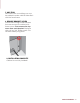
Swivel Units Models: AE46, AE42, ANE46, ANE42 (BOTTOM OF RACEWAY) 2 1 1 4 6 6 3 ELECTRICAL MODELS (AE46 SHOWN) NON- ELECTRICAL MODELS (ANE46 SHOWN) GET TO KNOW YOUR UNIT 1. CROSS BRACES - Three braces for 46” units - Two braces for 42” units 2. ELECTRICAL RACEWAY (AE46, AE42) 3. SIDE BRACKETS Tools Needed: - Stud Finder - 12-14” Level - Tape Measure - Small Flathead Screwdriver - Electric Drill (with 1/4” & 1/8” drill bit) - 1/4” Nut Driver (optional) - Safety Glasses - Utility Knife 4.
SWIVEL: PRE-INSTALLATION 1. DETERMINE MOUNTING HEIGHT Using the charts provided, determine the mounting height above floor (the distance between the floor and the bottom of the cabinet). First choose your desired ironing board height from the left column, then locate mounting height in the right column.
3. ENSURE ADEQUATE SPACE Refer to provided chart below to ensure adequate clearance for ironing. The cabinet door opens at 180 degrees; allow 16” from side of cabinet for door to fully open. AE46 AE42 ANE46 ANE42 1. Distance needed on either side of unit to fully swivel the board 1678” 145/8” 2. Distance from wall to tip of ironing board 507/8” 467/8” 3. Distance from wall to board when in full swivel position 321/2” 327/8” 24” 24” 4.
SWIVEL: RECESSED INSTALLATION Note: Instructions based on installation between 16” on-center studs. 3. PRE-DRILL HOLES 1. CUT WALL OPENING Your unit will be attached to the studs by screws in the upper and lower sides of the cabinet. Cut an opening into the wall based on unit dimensions given below. AE46/ANE46: 143/8” x 597/8” x 37/8” AE42/ANE42: 141/2” x 511/4 x 37/8” AE46, AE42: Remove electrical raceway before proceeding by removing the top and bottom screws on the raceway. 2.
MODELS AE46 & AE42: Refer to electrical instructions on pg.17 before proceeding to next step. 6. REMOVE BRACKET SCREW Locate side ironing board brackets that are secured to cabinet with three screws. Then remove the top screw from each bracket. This is where the bottom part of your cabinet will be secured to the studs. MODELS ANE46 & ANE42: Proceed to next step. DO NOT attempt to install your own electrical to unit. Warranty is voided if independent electrical is installed. 4.
SWIVEL: SURFACE MOUNT INSTALLATION 1. PREPARE CABINET Screws will be drilled through the upper and lower cross braces (see illustration on pg.3) inside the cabinet. Do not attempt to drill into hard board of cabinet. Determine location of screws, ensuring that the location of the mounting screw is as close to the center of the cabinet as possible. 2. PRE-DRILL PILOT HOLES Using a 1/4” drill bit, pre-drill holes in the upper and lower cross braces inside the cabinet as determined in previous step.
7. ADD TRIM Decorative trim or molding can now be added to make cabinet sides flush with the face frame. 8. REMOVE BRACKET SCREW Locate side ironing board brackets that are secured to cabinet with three screws. Then remove the top screw from each bracket. Replace with a #14 x 3/4” Phillips screw. This will add stability long-term. 9.
Non-Swivel Units Models: E46, E42, NE46, NE42 2 (BOTTOM OF RACEWAY) 1 3 4 5 ELECTRICAL MODELS (E46 SHOWN) 1 5 NON-ELECTRICAL MODELS (NE46 SHOWN) GET TO KNOW YOUR UNIT 1. CROSS BRACES - Three braces for 46” units - Two braces for 42” units 2. ELECTRICAL RACEWAY (E46, E42) 3. ELECTRICAL OUTLET Tools Needed: - Stud Finder - 12-14” Level - Tape Measure - Small Flathead Screwdriver - Electric Drill (with 1/4” & 1/8” drill bit) 10 - 1/4” Nut Driver (optional) - Safety Glasses - Utility Knife 4.
NON-SWIVEL: PRE-INSTALLATION 1. DETERMINE MOUNTING HEIGHT Using the charts provided at right, determine the mounting height above floor (the distance between the floor and the bottom of the cabinet) for your unit. First choose your desired ironing board height from the left column, then locate the mounting height in the right column.
3. ENSURE ADEQUATE SPACE Refer to provided chart to ensure adequate clearance for ironing. The cabinet door opens at 180 degrees; allow 16” from side of cabinet for door to fully open. Distance from wall to tip of ironing board Standing area clearance (not shown) The suggested distance from the side of the ironing where the user typically stands to ensure adequate space for ironing.
NON-SWIVEL: RECESSED INSTALLATION Note: Instructions based on installation between 16” on-center studs. 1. CUT WALL OPENING 3. PRE-DRILL HOLES 2. ATTACH CLEATS E46, E42: Remove electrical raceway before proceeding by removing the top and bottom screws on the raceway. Cut an opening into wall using the unit dimensions below: E46/NE46: 143/8” x 597/8” x 37/8” E42/NE42: 141/2” x 511/4 x 37/8” Your unit will be attached to the studs by screws in the upper and lower sides of the cabinet.
MODELS E46 & E42: Refer to electrical instructions on pg. 17 before proceeding to next step. 4. INSTALL UNIT INTO WALL MODELS NE46 & NE42: Proceed to next step. DO NOT attempt to install your own electrical to unit. Warranty is voided if independent electrical is installed. Make sure the cabinet is plumb and level. If needed, add shims to help unit fit space. Begin installation by carefully lifting unit into the wall opening. 5.
Non-Swivel: Surface Mount Installation 1. PREPARE CABINET Screws will be drilled through the upper and lower cross braces (see pg. 11) inside the cabinet. Do not attempt to drill into hardboard of cabinet. Determine location of screws, ensuring that the location of the mounting screw is as close to the center of the cabinet as possible. 2. PRE-DRILL HOLES Using a 1/4” drill bit, pre-drill holes in the upper and lower cross braces inside the cabinet as determined in previous step.
Electrical Instructions Models: AE46, AE42, E46, E42 ATTENTION! DISCONNECT ALL POWER BEFORE BEGINNING ELECTRICAL INSTALLATION. ALL ELECTRICAL MUST COMPLY WITH LOCAL AND NATIONAL CODES. IF YOU ARE UNFAMILIAR WITH ELECTRICAL WIRING, PLEASE CONTACT A QUALIFIED ELECTRICIAN TO COMPLETE THIS PORTION OF INSTALLATION. WARNING: The following electrical instructions are for models AE46, AE42, E46, E42 ONLY.
Position of Electrical Knockout for SURFACE MOUNT ONLY Ensure that power is disconnected at service entrance before proceeding. 1. REMOVE ELECTRICAL KNOCKOUT Open the front cover of the raceway by removing the screw at the top and bottom of the raceway. 241/2” Locate the electrical knockout, as specified on diagrams provided. Install a 3/8” romex connector where the knockout was removed. 213/16” Position of Electrical Knockout for RECESSED UNIT 21/2” 21/4” 11/4” DIA.
3. CONNECT WIRES Connect all power supply wires and ground wires in accordance with electrical codes. Trim supply wire as necessary. 4. REPLACE ELECTRICAL RACEWAY Place the raceway cover into position, ensuring that no wires are pinched. Reinstall the top and bottom screw to secure in place. Reconnect power supply and return to installation instructions.
220 W. Jackson St, Morton, IL 61550 1-800-536-9495 or info@emergacenter.