Owner’s Manual Ascender Elliptical Customer Service 1.800.750.IRON 1.800.750.4766 4009 Distribution Drive Suite 250 Garland, TX 75041 www.ironmanfitness.
Table of Contents Important Safety Information 3 Assembly 5 Monitoring Your Heart Rate 13 Warm-Up Exercises 14 Parts List 17 Exploded View 18 Warranty Information 19
Important Safety Information WARNING! Before using this unit or starting any exercise program, consult your physician. This is especially important for persons over the age of 35 and/or persons with pre-existing health problems. The manufacturer or distributor assumes no responsibility for personal injury or property damage sustained by or through the use of this product.
Important Safety Information Thank you for purchasing the Ironman Fitness Ascender Elliptical! The quality product you have chosen was designed to meet your needs for cardiovascular exercise. Before you start, please read the Owner’s Manual and become familiar with the operation of your new unit. Remember to take time to perform stretching exercises, provided in this manual, to help avoid injury.
Assembly Getting Started - The Ironman Fitness Ascender Elliptical will require some assembly. Unpack the box in a clear area. Remove packing material. Do not dispose of packing material until assembly is complete and unit is working properly. Place the unit on a clean level surface for assembly. Make sure there is easy access to an electrical outlet. Before assembling, the unit should be placed as close as possible to its final location.
Assembly Figure 2 CONSOLE TUBE COVER Figure 2 Locate bag labeled Figure 2. Locate cover. Secure cover to main frame by using three M5*0.8-12 screws on the left side of unit. Repeat for the right side. M5*0.8-12 SCREW Figure 3 CONSOLE TUBE Figure 3 Locate bag labeled Figure 3. Locate left and right handrail assemblies. Secure left handrail assembly to console tube by using one washer, one spring washer, one M10*20 hex bolt, and one end cap. Repeat for the right side.
Assembly Figure 4 Figure 4 Locate bag labeled Figure 4. Lift and place left linkage onto shaft sleeve and align holes. Secure linkage to unit using four M8*12 mm hex bolts. Repeat for right side. SLEEVE Note: The linkage is secured to the sleeve with three M8*12 hex bolts on the top of the linkage and one M8*12 hex bolt on the bottom of the linkage. LINKAGE M8*12 HEX BOLT Figure 5 Locate bag labeled Figure 5. Locate right pedal tube assembly.
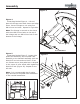
Assembly Figure 6 Figure 6 Locate bag labeled Figure 6. Locate bracket covers. Attach bracket cover to the handrail assembly by lining up hole, and securing using one screw, M5*0.8-12. Repeat for other side. HANDRAIL ASSEMBLY SCREW Note: Do not overtighten screw, this will damage bracket cover. BRACKET COVER Figure 7 RIGHT HANDLEBAR LEFT HANDLEBAR CONSOLE TUBE Figure 7 Locate bag labeled Figure 7. Locate Handlebars. Attach Left Handlebar to Handlebar Assembly using three M8*16mm Hex Bolts.
Assembly Figure 8 Figure 8 Locate pulse handlebar assembly. Feed the pulse wires coming from the pulse handlebar assembly up the console tube. PULSE WIRE PULSE HANDLEBAR ASSEMBLY Figure 9 Figure 9 Locate bag labeled Figure 9. Secure pulse handlebar assembly to console tube using six M6*1.0 hex socket head bolts. Note: Ensure that all wires are secure inside console tube. Be careful not to pinch wires.
Assembly Figure 10a Figure 10b Figure 10 Step 1: Locate console. Remove the back cover of the console by unscrewing the two screws (figure 10a). Feed cables coming from the unit through the hole located on the bottom of the back cover (figure 10b). Step 2: Connect the coaxial cable coming from the unit to the coaxial input located on the console. Note: For optimal reception, ensure that the coaxial cable is firmly tightened.
Assembly Figure 11 Figure 11 Locate bag labeled Figure 11. Secure console to console tube using four M5*0.8mm hex bolts. Note: The console will be attached to the console mounting bracket that is located on the top of the console tube. This will allow the console to be tilted forward or backwards when desired. M5*0.8MM HEX BOLT Console Mounting Bracket Figure 12 Figure 12 Secure bottle holder to console tube using two M5*0.8-12 Screws. M5*0.8-12.
Assembly CONGRATULATIONS! You have completed assembly of your Ascender Elliptical.
Monitoring Your Heart Rate Monitoring Your Heart Rate To obtain the greatest cardiovascular benefits from your exercise workout, it is important to work within your target heart rate zone. The American Heart Association (AHA) defines this target as 60%-75% percent of your maximum heart rate. Your maximum heart rate may be roughly calculated by subtracting your age from 220. Your maximum heart rate and aerobic capacity naturally decreases as you age.
Warm Up Exercises EXERCISE GUIDELINES WARNING! Before beginning this or any exercise program, you should consult your physician. This is especially important for individuals over the age of 35 or individuals with pre-existing health problems. Flexibility is a key to fitness. Stretch all major muscle groups at least two to three times per week after a 5 to 10 minute warmup. Stretch just to the point of a gentle tug. If you have back, joint, or other health problems, talk to your doctor first.
Warm Up Exercises WARNING! Before beginning this or any exercise program, you should consult your physician. This is especially important for individuals over the age of 35 or individuals with pre-existing health problems. Wrist Extensor Extend your right arm in front of you with your palm up and your elbow straight. Point your fingertips toward the floor by bending at the wrist. Using your left hand, pull the back of your right hand toward you gently.
Warm Up Exercises WARNING! Before beginning this or any exercise program, you should consult your physician. This is especially important for individuals over the age of 35 or individuals with pre-existing health problems. Calf Stretch Face a solid structure such as a wall with your left foot ahead of your right, toes straight ahead. Bend your left knee, press your hips forward, and lean into the wall. Keep both heels down, your right leg straight, and you left knee over your ankle.
Parts List Ascender Parts List Rev A Ref Part # Description Qty Ref Part # Description Qty 0J3P 302-01444 ALLEN WRENCH, REXON 1 2GQU 306-00812 END CAP, FRAME ASCENDER 2 0J3R 302-00142 WRENCH HEX.
G 2LXT 2 J 2CTC 0K2W3 2 21X83 2HNU 4 0KN22 2N3N2 0KR0 2 2CU9 2 Q 22LR 2CU74 2J78 2CU8 2 0J93 2 2H4J 0JEG 2CTQ 0J4Z 2 2KX8 2 2CS3 N 2MZJ 0K712 J 8 Q 2J6C 2 2CRJ 0KRK 16 2DUD6 C 2MYG 2N55 2LGS 2 H 2KX9 4 294S 2 22QV 2 2N57 22QV 2 @2N53 2GQN 2GPG 2 0J93 2 21LG 2 2DM42 2KX9 4 2GQP2 0K4T 24 4 F K 2H66 27JR 0K94 16 2N5H2 0K4R 4 2DUW2 2KX9 8 @2H7B 21NP2 D L K 0J6C 3 2CU3 2 2HMD3 0K2C 4 0KR0 2 2N59 H 2N5K G 26LH 4 0KNM4 I 2DAK D 2GTT
Warranty Information Residential and Personal Use Limited Warranty PLEASE READ THESE WARRANTY TERMS AND CONDITIONS FULLY AND CAREFULLY BEFORE USING YOUR IRONMAN FITNESS EQUIPMENT. BY USING THE EQUIPMENT, YOU ARE CONSENTING TO BE BOUND BY THE FOLLOWING TERMS AND CONDITIONS.
Customer Service 1.800.750.IRON 1.800.750.4766 Ironman Fitness 4009 Distribution Drive Suite 250 Garland, TX 75041 www.ironmanfitness.com Ironman, Ironman Triathlon and M-dot are registered trademarks of the World Triathlon Corporation. This product is licensed by the Ironman Triathlon.