BX SYSTEM INSTALLATION © 2021 IRONRIDGE, MANUAL INC. VERSION 2.
Contents DISCLAIMER 1 RATINGS 2 MARKINGS 2 CHECKLIST 3 OVERVIEW 4 INSTALLATION STEPS (QUICK GUIDE) 5 1. MARK LAYOUT 6 2. PLACE CHASSIS 6 3. MOUNT MLPE (OPTIONAL) 6 4. LAY BALLAST 7 5. ANCHOR SYSTEM (OPTIONAL) 7 6. INSTALL MODULES 8 7. COMPLETE BONDING 8 8.
RATINGS UL 2703 LISTED #5014158 Conforms to STD UL 2703 (2015) Standard for Safety First Edition: Mounting Systems, Mounting Devices, Clamping/ Retention Devices, and Ground Lugs for Use with Flat-Plate Photovoltaic Modules and Panels. • • • • • Max Overcurrent Protective Device (OCPD) Rating: 40A Max Module Size: 30.5ft² Module Orientation: Landscape System Level Allowable Design Load Rating: 30 PSF downward, 15 PSF upward, 5 PSF lateral.
CHECKLIST PRE-INSTALLATION COMPONENTS ☐ Verify module compatibility. See Page 11 for info.
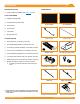
OVERVIEW BX CHASSIS (5° & 10°) BX Chassis is designed to clamp PV modules and secure them in place. Reference tabs are integrated to aid with aligning modules according to system layout. The Chassis is available in two SKUs: 5 and 10 degree tilt configurations. The Chassis is designed to accommodate 4 full size (16” x 8” x 4”) or 8 half-size concrete ballast blocks (16” x 8” x 2”) nominal dimensions.
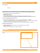
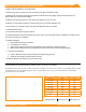
INSTALLATION STEPS (QUICK GUIDE) 1. Mark out all fire setbacks on the roofing plane. 2. Measure and mark out footprint of array according to the approved planset location. 3. Starting at the south edge of the approved planset, chalk the South Array Edge, making sure that this line is at least 8" away from the South Fire Setback. 4. Measure Chassis spacing (refer to chart below) and chalk out 3 rows, 25’ each. 5. Measure out the Chassis locations by marking along each row, module width plus 3/8”. 6.
1. MARK LAYOUT Using the approved planset, mark out all fire setbacks and the array foot print on the roof(s). Mark the South Array Edge with a 25' line (for example). If the southern edge of the array is against the South Fire Setback, mark the South Array Edge at least 8" away from the setback. This will ensure that no part of the Chassis is in the setback. Measure Chassis spacing (refering to table on Page 5) and chalk out 3x 25' rows.
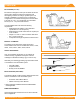
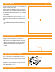
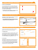
4. LAY BALLAST Place ballast blocks in BX Chassis as indicated on site layout. 5. ANCHOR SYSTEM (OPTIONAL) A. SECURE L-FEET A The Attachment Kit uses an 8' minimum Galvanized Strut Channel with slotted holes to span across two Chassis and a Flat Roof Attachment(FRA) Anchor in order to anchor the Chassis to the roof. Secure L-Feet onto the Chassis by installing the Carriage Bolt and Square Washer from the underside of each Chassis through the reference hole. Torque Flange Nut to 120 in-lbs.
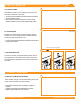
6. INSTALL MODULES A. PLACE CLAMPS A Place Bottom Clamp over the Chassis' corner bolt, then pull clamp towards the outer edge. ➢ The north end of the North Row and south end of the South Row do not need bottom clamps. ➢ When a Chassis is shifted inwards under a module, clamps should be installed on all corner bolts supporting the module. B. LAY MODULES B Lay Module onto Bottom Clamps Starting in the South-West corner and working east, lay modules in a row onto edge of Bottom Clamps.
7. COMPLETE BONDING (CONTINUED) B. ROW-TO-ROW BONDING B The 38" Bonding Jumper is an electrial bonding jumper that should be used for row to row bonding by securing Clips to inner flanges on long side of a module from each row, as shown. Tapping Clips into place may be required for modules with thicker flanges. ➢ The bonding does not need to take place on the same side of the array, so long as every row is bonded to the next row. 8.
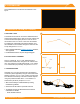
ELECTRICAL DIAGRAM © 2021 IRONRIDGE, INC. VERSION 2.
3. MODULE Secure COMPATIBILITY Lugs The BX System may be used to ground and/or mount a PV module complying with UL 2703 only when the specific module has been evaluated for grounding and/or mounting in compliance with the included instructions. Unless otherwise noted, “xxx” refers to the module power rating and both black and silver frames are included in the certification.
MODULE COMPATIBILITY Ecosolargy Ecosolargy modules with 35, 40, and 50 mm frames ECOxxxYzzA-bbD Where “Y” can be A, H, S, or T; “zz” can be 125 or 156; “A” can be M or P; “bb” can be 60 or 72; and “D” can be blank or B ET Solar ET Solar modules with 30, 35, 40, and 50 mm frames ET-YZZZxxxAA Where "Y" can be P, L, or M; "ZZZ" can be 660, 660BH, 672, 672BH, 754BH, 766BH, 772BH; and "AA" can be GL, TB, TW, WB, WW, BB, WBG, WWG, WBAC, WBCO, WWCO, WWBCO or BBAC Flex Flex modules with 35, 40, and 50 mm frame
MODULE COMPATIBILITY JA Solar JA Solar modules with 30, 35, 40 and 45 mm frames JAyyzz-bbww-xxx/aa Where “yy” can be M, P, M6 or P6; “zz” can be blank, (K), (L), (R), (V), (BK), (FA), (TG), (FA)(R), (L)(BK), (L) (TG), (R)(BK), (R)(TG), (V)(BK), (BK)(TG), or (L)(BK)(TG); “bb” can be 48, 60, 66, 72 or 78; "ww" can be D09, D10, D20, D30, S01, S02, S03, S06, S09, S10, S12, S20 or S30; and “aa” can be BP, MB, MR, SI, SC, PR, 3BB, 4BB, 4BB/RE, 5BB Jinko Jinko modules with 35 and 40 mm frames JKMYxxxZZ-aa Wher
Module Compatibility Recom Recom modules with 35 and 40 mm frames RCM-xxx-6yy Where “yy” can be MA, MB, ME or MF REC Solar REC modules with 30, 38 and 45 mm frames RECxxxYYZZ Where “YY” can be AA, M, NP, NP2, PE, PE72, TP, TP2, TP2M, TP2SM, TP2S, TP3M or TP4; and “ZZ” can be blank, Black, BLK, BLK2, SLV, 72, or Pure Renesola ReneSola modules with 35, 40 and 50 mm frames AAxxxY-ZZ Where "AA" can be SPM(SLP) or JC; "Y" can be blank, F, M or S; and "ZZ" can be blank, Ab, Ab-b, Abh, Abh-b, Abv, Abv-b, Bb,
Module Compatibility SunEdison SunEdison Modules with 35, 40 & 50 mm frames SE-YxxxZABCDE Where "Y" can be B, F, H, P, R, or Z; "Z" can be 0 or 4; "A" can be B,C,D,E,H,I,J,K,L,M, or N ; "B" can be B or W; "C" can be A or C; "D" can be 3, 7, 8, or 9; and "E" can be 0, 1 or 2 Suniva Suniva modules with 35, 38, 40, 46, and 50 mm frames OPTxxx-AA-B-YYY-Z MVXxxx-AA-B-YYY-Z Where "AA" is either 60 or 72; "B" is either 4 or 5; "YYY" is either 100,101,700,1B0, or 1B1; and "Z" is blank or B Sunpower Sunpower st