
Install Manual
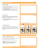
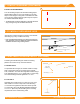
Table Of Contents
- DISCLAIMER
- RATINGS
- MARKINGS
- Checklist
- OVERVIEW
- INSTALLATION STEPS (QUICK GUIDE)
- 1. MARK LAYOUT
- 2. PLACE CHASSIS
- 3. MOUNT MLPE (OPTIONAL)
- 4. LAY BALLAST
- 5. ANCHOR SYSTEM (OPTIONAL)
- 6. INSTALL MODULES
- 7. COMPLETE BONDING
- 8. PV Module GROUNDING LUGS
- string INVERTER MOUNTING KIT (OPTIONAL)
- ELECTRICAL DIAGRAM
- MODULE COMPATIBILITY

CONTENTS
©
2021 IRONRIDGE, INC. VERSION 2.1
BX SYSTEM INSTALLATION MANUAL - 1
DISCLAIMER 1
RATINGS 2
MARKINGS 2
CHECKLIST 3
OVERVIEW 4
INSTALLATION STEPS (QUICK GUIDE) 5
1. MARK LAYOUT 6
2. PLACE CHASSIS 6
3. MOUNT MLPE (OPTIONAL) 6
4. LAY BALLAST 7
5. ANCHOR SYSTEM (OPTIONAL) 7
6. INSTALL MODULES 8
7. COMPLETE BONDING 8
8. PV MODULE GROUNDING LUGS 9
STRING INVERTER MOUNTING KIT (OPTIONAL) 9
ELECTRICAL DIAGRAM 10
MODULE COMPATIBILITY 11
MODULE COMPATIBILITY 12
MODULE COMPATIBILITY 13
MODULE COMPATIBILITY 14
MODULE COMPATIBILITY 15
DISCLAIMER
This manual describes proper installation procedures and provides necessary standards required for product reliability.
Warranty details are available at IronRidge.com. All installers must thoroughly read this manual and have a clear
understanding of the installation procedures prior to installation. Failure to follow these guidelines may result in property
damage, bodily injury or even death.
IT IS THE INSTALLER’S RESPONSIBILITY TO:
• Ensure safe installation of all electrical aspects of the array. All electrical installation and procedures should be
conducted by a licensed and bonded electrician or solar contractor. Routine maintenance of a module or panel shall
not involve breaking or disturbing the bonding path of the system. All work must comply with national, state and local
installation procedures, product and safety standards.
• Comply with all applicable local or national building and re codes, including any that may supersede this manual.
• Ensure all products are appropriate for the installation, environment, and array under the site’s loading conditions.
• Use only IronRidge parts or parts recommended by IronRidge; substituting parts may void any applicable warranty.
• Review the Design Assistant to conrm design specications.
• Ensure provided information is accurate. Issues resulting from inaccurate information are the installer’s responsibility.
• Ensure bare copper grounding wire does not contact aluminum and zinc-plated steel components, to prevent risk of
galvanic corrosion.
• If loose components or loose fasteners are found during periodic inspection, re-tighten immediately. Any components
showing signs of corrosion or damage that compromise safety shall be replaced immediately.
• Provide an appropriate method of direct-to-earth grounding according to the latest edition of the National Electrical
Code, including NEC 250: Grounding and Bonding, and NEC 690: Solar Photovoltaic Systems.
• Disconnect AC power before servicing or removing modules, AC modules, microinverters and power optimizers.
• Review module manufacturer’s documentation for compatibility and compliance with warranty terms and conditions.
CAUTION: Module removal may disrupt the bonding path and could introduce the risk of electric shock. If during servicing
a module is required to be removed, a bonding jumper shall be installed between the adjacent modules from where the
module was removed to maintain the bond path.