
Install Manual

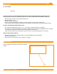
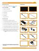
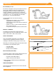
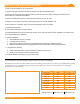
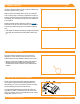
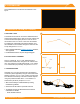
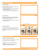
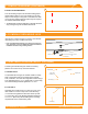
Table Of Contents
- DISCLAIMER
- RATINGS
- MARKINGS
- Checklist
- OVERVIEW
- INSTALLATION STEPS (QUICK GUIDE)
- 1. MARK LAYOUT
- 2. PLACE CHASSIS
- 3. MOUNT MLPE (OPTIONAL)
- 4. LAY BALLAST
- 5. ANCHOR SYSTEM (OPTIONAL)
- 6. INSTALL MODULES
- 7. COMPLETE BONDING
- 8. PV Module GROUNDING LUGS
- string INVERTER MOUNTING KIT (OPTIONAL)
- ELECTRICAL DIAGRAM
- MODULE COMPATIBILITY

©
2021 IRONRIDGE, INC. VERSION 2.1
BX SYSTEM INSTALLATION MANUAL - 5
INSTALLATION STEPS (QUICK GUIDE)
1. Mark out all re setbacks on the roong plane.
2. Measure and mark out footprint of array according to the approved planset location.
3. Starting at the south edge of the approved planset, chalk the South Array Edge, making sure that this line is at
least 8" away from the South Fire Setback.
4. Measure Chassis spacing (refer to chart below) and chalk out 3 rows, 25’ each.
5. Measure out the Chassis locations by marking along each row, module width plus 3/8”.
6. Place Chassis on cross hairs. Align cross hairs with alignment marks on Chassis.
7. Install MLPE as needed.
8. Load Chassis with blocks as per the plan set.
9. Install xed attachment points as required by the plan set for anchored hybrid systems, seal/ash in accordance with
the roong manufacturer’s guidelines.
10. Module Installation
a. Place all Bottom Clamps on Chassis.
b. Land all panels on Chassis.
c. Place all Top Clamps and ensure proper alignment and engagement of the Bottom Clamp.
d. Make sure that all Clamps are fully engaged and square to the module and torqued appropriately.
11. Complete Array Bonding
a. Install 8” Module Bonding Jumpers between all modules along the rows.
b. Install 38” Row Bonding Jumpers between all rows.
12. Install PV Module Grounding Lug to ground each array.
It can be helpful on constrained arrays to chalk line every row, but it is not required.
e illustration below shows the order of chalk operations for marking out the starter array, as well as a corresponding Chassis spacing
table which can be used to easily nd the approx. Chassis spacing within 1/8". For more precise measurements use the formulas
provided at the bottom of the table.
Module Width 5° Chassis Spacing 10° Chassis Spacing
38.5" - 39" 48.5" 51"
39" - 39.5" 49" 51.5"
39.5" - 40" 49.5" 52"
40" - 40.5" 50" 52.5"
40.5" - 41" 50.5" 53"
41" - 41.5" 51" 53.5"
41.5" - 42" 51.5" 54"
42" - 42.5" 52" 54.5"
42.5"+ 52.5" 55"
Spacing Formulas: Width Cos(5°) + 10" Width Cos(10°) + 13”