
Install Manual

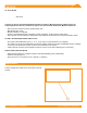
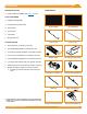
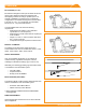
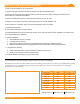
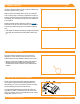
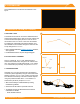
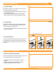
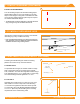
Table Of Contents
- DISCLAIMER
- RATINGS
- MARKINGS
- Checklist
- OVERVIEW
- INSTALLATION STEPS (QUICK GUIDE)
- 1. MARK LAYOUT
- 2. PLACE CHASSIS
- 3. MOUNT MLPE (OPTIONAL)
- 4. LAY BALLAST
- 5. ANCHOR SYSTEM (OPTIONAL)
- 6. INSTALL MODULES
- 7. COMPLETE BONDING
- 8. PV Module GROUNDING LUGS
- string INVERTER MOUNTING KIT (OPTIONAL)
- ELECTRICAL DIAGRAM
- MODULE COMPATIBILITY

©
2021 IRONRIDGE, INC. VERSION 2.1
BX SYSTEM INSTALLATION MANUAL - 6
1. MARK LAYOUT
Place rst Chassis at Southwest corner of the array,
aligning the center reference hole with the cross hair
marker. Repeat for each additional Chassis in the array.
➢ After the array has been installed, the Chassis at the East and
West edges of the array should be moved inward from the
perimeter reference lines so that they are fully underneath the
modules.
2. PLACE CHASSIS
Using the approved planset, mark out all re setbacks and
the array foot print on the roof(s).
Mark the South Array Edge with a 25' line (for example).
If the southern edge of the array is against the South Fire
Setback, mark the South Array Edge at least 8" away from
the setback. This will ensure that no part of the Chassis is
in the setback.
Measure Chassis spacing (refering to table on Page 5)
and chalk out 3x 25' rows. Then measure out the Chassis
locations by marking along each row (module width plus
3/8").
➢ These layouts are useful for maintaining a straight line at the start
of the array. Once started the rest of the system is build as you
go.
Mount microinverters and power optimizers directly to
the Chassis using the MLPE Mounting Hardware Kit.
Alternatively, you can use a third party module mounting
bracket (following manufacturer instructions).
To install the MLPE Mounting Hardware Kit, place the
Cage Nut into either of the square cut-outs on the lower
edge of a Chassis. Secure your MLPE device with a 5/16"
Flange Bolt torqued to 60 in-lbs.
3. MOUNT MLPE (OPTIONAL)
60 in-lbs