
Install Manual
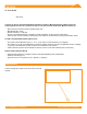
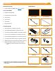
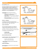
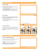
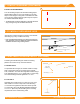
Table Of Contents
- DISCLAIMER
- RATINGS
- MARKINGS
- Checklist
- OVERVIEW
- INSTALLATION STEPS (QUICK GUIDE)
- 1. MARK LAYOUT
- 2. PLACE CHASSIS
- 3. MOUNT MLPE (OPTIONAL)
- 4. LAY BALLAST
- 5. ANCHOR SYSTEM (OPTIONAL)
- 6. INSTALL MODULES
- 7. COMPLETE BONDING
- 8. PV Module GROUNDING LUGS
- string INVERTER MOUNTING KIT (OPTIONAL)
- ELECTRICAL DIAGRAM
- MODULE COMPATIBILITY

©
2021 IRONRIDGE, INC. VERSION 2.1
BX SYSTEM INSTALLATION MANUAL - 7
4. LAY BALLAST
Place ballast blocks in BX Chassis as indicated on site
layout.
A. SECURE L-FEET
The Attachment Kit uses an 8' minimum Galvanized Strut
Channel with slotted holes to span across two Chassis and
a Flat Roof Attachment(FRA) Anchor in order to anchor
the Chassis to the roof. Secure L-Feet onto the Chassis
by installing the Carriage Bolt and Square Washer from
the underside of each Chassis through the reference hole.
Torque Flange Nut to 120 in-lbs.
➢ Refer to Flat Roof Attachment installation instructions for details,
where applicable.
➢ Flat Roof Attachment Kit is not part of the grounding path.
B. ATTACH STRUT CHANNEL
Secure, at minimum, an 8’ x 1-5/8" Galvanized Strut
Channel with slotted holes, through the two Chassis onto
the L-Feet using the provided 3/8" Bolt with 1-1/4" washer
to a Channel Nut (not provided). Torque Nut to 250 in-lbs.
C. FINISH ANCHORS
Assemble an L-Foot onto the FRA Anchor and ashing
membrane (where applicable) using the 3/8” Bolt and Flat
Washer torqued to 250 in-lbs. Then, install L-Foot and Flat
Roof Attachment assembly at the Strut Channel midpoint
using the provided 3/8" Bolt with a 1-1/4" Washer to a
Channel Nut (as before) torqued to 250 in-lbs.
➢ After anchor assembly is installed seal/ash per roong
manufacturer’s guidelines.
➢ Anchors shall not be located on a perimeter south row.
➢ The following 3rd party roof attachment has been tested or
evaluated for use with BX:
• Anchor Products U-Anchors
5. ANCHOR SYSTEM (OPTIONAL)
A
B
C
Flange Nut
L-Foot
Square
Washer
Carriage
Bolt
120 in-lbs
250 in-lbs
120 in-lbs