
Install Manual

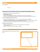
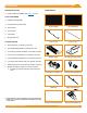
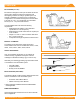
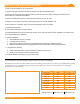
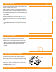
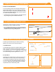
Table Of Contents
- DISCLAIMER
- RATINGS
- MARKINGS
- Checklist
- OVERVIEW
- INSTALLATION STEPS (QUICK GUIDE)
- 1. MARK LAYOUT
- 2. PLACE CHASSIS
- 3. MOUNT MLPE (OPTIONAL)
- 4. LAY BALLAST
- 5. ANCHOR SYSTEM (OPTIONAL)
- 6. INSTALL MODULES
- 7. COMPLETE BONDING
- 8. PV Module GROUNDING LUGS
- string INVERTER MOUNTING KIT (OPTIONAL)
- ELECTRICAL DIAGRAM
- MODULE COMPATIBILITY

©
2021 IRONRIDGE, INC. VERSION 2.1
BX SYSTEM INSTALLATION MANUAL - 8
6. INSTALL MODULES
A. PLACE CLAMPS
Place Bottom Clamp over the Chassis' corner bolt, then
pull clamp towards the outer edge.
➢ The north end of the North Row and south end of the South Row
do not need bottom clamps.
➢ When a Chassis is shifted inwards under a module, clamps
should be installed on all corner bolts supporting the module.
B. LAY MODULES
Starting in the South-West corner and working east, lay
modules in a row onto edge of Bottom Clamps. Double-
check panel spacing along each row.
➢ You can use reference tabs located in the middle of the Chassis to
properly space modules.
C. SECURE MODULES
To secure a module, rst pull the Bottom Clamp until it is
snug against the inner ange of the module. Then place
the Top Clamp and Flange Nut over the bolt and torque to
120 in-lbs.
A. MODULE-TO-MODULE BONDING
The 8” Bonding Jumper is an electrial bonding jumper that
can be used for module to module bonding.
➢ New jumpers should be used if re-installation of jumper is
required.
➢ Jumpers are installed on the bottom ange of modules.
➢ Supports ange thicknesses 1.2mm to 3.1mm.
7. COMPLETE BONDING
A
A
B
C
Reference Tab Properly Gaps Modules
Lay Module onto
Bottom Clamps
120 in-lbs