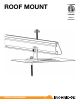
ROOF MOUNT 4008083 *Class A* Fire Rated INSTALLATION MANUAL
Contents DISCLAIMER 1 RATINGS 1 CHECKLIST 2 PRIMARY COMPONENTS 3 1. ATTACH BASES 3 2. PLACE RAILS 3 3. SECURE LUG 4 4. CLAMP MODULES 4 EXPANSION JOINTS 5 ELECTRICAL DIAGRAM 5 OPTIONAL COMPONENTS 6 ALTERNATIVE LUGS 6 FLASHFOOT 6 END CAPS 7 WIRE CLIPS 7 STANDOFFS 7 TILT LEGS 8 WARRANTY 9 DISCLAIMER This manual describes the proper installation procedures and provides minimum standards required for product reliability and warranty.
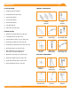
CHECKLIST TOOLS REQUIRED PRIMARY COMPONENTS ☐☐ Cordless Drill (non-impact) 204 in-lbs ☐☐ Torque Wrench (0-240 in-lbs) ☐☐ 5/16” Socket (deep) ☐☐ 7/16” Socket (deep) XR Rail ☐☐ 9/16” Socket (deep) L-Foot Aluminum Aluminum ☐☐ 1/8" Allen Wrench 84 & 20 in-lbs ☐☐ 3/8” Socket (for Tilt Legs) TORQUE VALUES ☐☐ FlashFoot Lag Bolts (5/16"-9): Fully seat ☐☐ L-Feet Nuts (3/8"-16): 204 in-lbs ☐☐ Internal Splice Screws (1/4"-14): Fully seat Internal Splice Aluminum Grounding Strap Tinned Copper 84 in-lbs 8
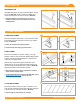
PRIMARY COMPONENTS Components in this section are classified for Integrated Grounding (UL 2703). Follow these installation procedures to ensure compliance with the following standards: INTEGRATED GROUNDING PER UL 2703 STRUCTURAL CODE PER ASCE 7-10 1-3 CLASS A FIRE RATED PER UL 1703 WITH TYPE 1, 2, & 3 SOLAR MODULES (FLUSH MOUNT, ANY ROOF SLOPE, ANY MODULE TO ROOF GAP, NO PERIMETER GUARDING REQUIRED) 1. ATTACH BASES ROOF ATTACHMENTS Install base attachments.
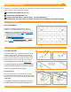
3. SECURE LUG GROUNDING LUG Hex Nut (84 in-lbs) Assemble Grounding Lug with provided hardware. Torque hex nut to 84 in-lbs. Install a minimum 10 AWG solid copper grounding wire. Torque set screw to 20 in-lbs. Set Screw (20 in-lbs) ▶▶ Grounding hardware is only needed on one rail per row of modules. Grounding Lugs must be installed on same rail as Grounding Straps. 4. CLAMP MODULES A. FIRST END CLAMPS A Place first module a minimum of 1.5" from rail ends.
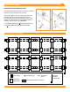
EXPANSION JOINTS GROUNDING STRAP EXPANSION JOINT 3/8" From End Grounding Strap Expansion Joints are required for thermal expansion of rows exceeding 100 feet of rail. Torque to 84 in-lbs Insert Internal Splice into first rail and secure with screw. Assemble and secure Grounding Strap 3/8" from rail end. Slide second rail over Internal Splice leaving 1" gap between rails. Attach other end of Grounding Strap with hardware, and torque hex nuts to 84 in-lbs.
OPTIONAL COMPONENTS The markings below indicate that the component complies with or does not violate requirements of the listing indicated: INTEGRATED GROUNDING PER UL 2703 STRUCTURAL CODE COMPLIANCE PER ASCE 7-10 1&2 3 CLASS A FIRE RATED PER UL 1703 WITH TYPE 1 & 2 MODULES (TILT MOUNT, ANY ROOF SLOPE)* CLASS A FIRE RATED PER UL 1703 WITH TYPE 3 MODULES (TILT MOUNT, < 9.5 DEGREE ROOF SLOPE)* *APPLICABLE TO ANY MODULE TO ROOF GAP FOR MODULE TILT OF 1 DEGREE AND HIGHER. DOES NOT REQUIRE PERIMETER GUARDING.
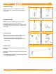
END CAPS 1-3 End Caps add a completed look and keep debris and pests from collecting inside rail. Firmly press End Cap onto rail end. íí End Caps come in sets of left and right. Check that the proper amount of each has been provided. WIRE CLIPS 1-3 Wire Clips offer a simple wire management solution. Press Clip into Slot Firmly press Wire Clip into top rail slot. Run electrical wire through open clip. Snap closed once all wires have been placed.
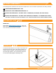
TILT LEGS 1&2 3 A. SOUTH TILT LEGS A Mount South Tilt Legs to roof attachments. Use the torque specifications required by the roof attachment manufacturer. B. NORTH TILT LEGS B Mount U-Feet to roof attachments, using the torque specifications required by the roof attachment manufacturer. Place North Tilt Legs into U-Feet, inserting 3/8”-16 bolts with washers into holes and attaching nuts. Finger tighten. C.
Warranty Effective for Products manufactured after April 1st, 2012, IronRidge provides the following warranties, for Products installed properly and used for the purpose for which the Products are designed: (a) Products with finishes (ie excluding without limitation Products that are mill finished) shall be free of visible defects, peeling, or cracking, under normal atmospheric conditions, for a period of three years from the earlier of (i) the date of complete installation of the Product or (ii) 30 days af