FX SYSTEM INSTALLATION MANUAL
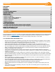
CONTENTS DISCLAIMER RATINGS MARKINGS CHECKLIST FX SYSTEM COMPONENTS DESIGN GUIDELINES INSTALLATION 1. LAY OUT ARRAY 2. INSTALL FLASH FX 3. INSTALL FIRST ROW OF MOUNT FX 4. INSTALL TRIM AND BRIDGE FX 5. INSTALL MODULES 6. INSTALL LUG FX 7. WIRE MANAGEMENT ARRAY MAINTENANCE 1. ACCESS FROM NORTH EDGE (MODULE REPLACEMENT) 2.
RATINGS UL 2703 LISTED #5003807 • Conforms to STD UL 2703 (2015) Standard for Safety First Edition: Mounting Systems, Mounting Devices, Clamping/ Retention Devices, and Ground Lugs for Use with Flat-Plate Photovoltaic Modules and Panels. • Max Overcurrent Protective Device (OCPD) Rating: 25A • Max Module Size: 20ft² • Module Orientation: Portrait or Landscape • Allowable Design Load Rating: 30 PSF downward, 20 PSF upward, 10 PSF lateral.
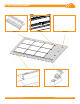
FX SYSTEM COMPONENTS Bridge FX Lug FX Trim FX & End Cap © 2018 IRONRIDGE, INC. VERSION 1.
FX SYSTEM COMPONENTS MOUNT FX Mount FX is uniquely designed to securely grip PV modules and secure them in place. The base of the Mount FX assembly allows for 360 degree articulation. This provides North-South flexibility and also helps to avoid conflict with the Bridge FX. A built-in wire management trough and integrated bonding features allow for a fullybonded solution and seamless, rapid installation.
FX SYSTEM COMPONENTS LUG FX Use the Lug FX to ground/earth a single PV Array. Attach to any Bridge FX on north edge of an array. Only one Grounding Lug required per continuous array, regardless of array size. Lug FX TRIM FX Trim FX provides a seamless and finished aesthetic appearance. It also aids in the installation of the first row of modules. Trim FX END CAPS End Caps are installed on the ends of Trim FX. Only two End Caps are required per row of Trim FX. They create a seamless aesthetic finish.
DESIGN GUIDELINES The information provided in this installation manual provides the end user with the information needed to custom-build and install a PV array on a composition shingle roof. Use the notes below as a guide when designing your PV array.
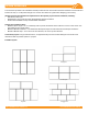
DESIGN GUIDELINES Thermal Expansion Guidelines: • The Bridge FX spacer is used to align modules and maintain the module gap. It also provides compliance in thermal expansion and contraction. This eliminates the need for a thermal expansion joint and does not limit array size. Spacer Maximum and Minimum Cantilever Rules: • Maximum Cantilever = 1/3 of maximum span away from edge of module for both landscape and portrait orientations.
DESIGN GUIDELINES Module Support: • Each module must have at least one Mount FX on the North and South edges. This applies in both Landscape and Portrait orientations. Flashing Location (Shingle Rule): • Flash FX should not overhang a shingle drip edge by more than ¼”. • Hole location must be a minimum of 2-3/4" above shingle edge. • If the hole location lands less than 2 3/4" from the shingle drip edge, mark it for reference.
DESIGN GUIDELINES Bridge FX Application: • A bridge is required at every Cross Roof module gap location, unless the cantilever of the adjacent modules is less than 1/3 of the maximum span. • A bridge is required at every Trim FX union location in the Cross Roof direction. This maintains continuity in the array through electrical bonding. • Bridges located on the northernmost edge of an array will require thumb screws to lock them into place (refer to page 16 for detailed instructions).
INSTALLATION STEPS The steps laid out in the following pages explain in detail how to properly lay out and install FX System components. They also cover information on wiring your system, wire management, and module replacement. 1. LAY OUT ARRAY A A. MARK PERIMETER Determine the position of your array and mark off the perimeter on the roof. B. FIND ATTACHMENT LOCATIONS Locate rafters and mark the location for the first row of attachments. This will typically be 3" from the bottom edge of the shingle.
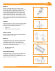
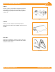
3. INSTALL FIRST ROW OF MOUNT FX A. SECURE OUTER MOUNTS A 7/16" socket 132 in-lbs Secure two mounts on either end of the first row to the flashings with hanger nuts. Position each mount so that the hanger bolt is centered on the slot. Torque to 132 in-lbs. B. INSTALL MOUNTS Hanger bolt centered B Attach a string line to the two outermost mounts. Run the string over the top of the mounts.
3. INSTALL FIRST ROW OF MOUNT FX C. ADJUST MOUNT FX HEIGHT C If needed, mounts can be lowered and raised in order to accommodate any roof undulations. tical Ver p of Bolt To To lower the module height, rotate the drive nut clockwise. To raise the module height, rotate the drive nut counterclockwise. The total height adjustability of Mount FX is 1". Mount FX is pre-assembled to half of that range. Pre-Assembled Position Lowest Position Highest Position 4. INSTALL TRIM FX AND BRIDGE FX A.
4. INSTALL TRIM FX AND BRIDGE FX B B. CONNECT TRIM FX TO BRIDGE FX Connect the second trim to the bridge using the same method. Repeat for remaining trim and bridge assemblies. Always position the ends of Trim FX so that it is centered between alignment markers. The distance between one Bridge FX bolt spacer to the next should equal the module dimension being installed. C. INSTALL END CAPS Install one End Cap on each end of the connected length of Trim FX (running E-W along the bottom of the array). 5.
5. INSTALL MODULES B. ATTACH NORTH EDGE B Once module is almost parallel to the roof, align mount with hanger bolt and pivot onto the north edge of the module. Secure mount to the flashing using the hanger nut. Torque to 132 in-lbs. 7/16" socket 132 in-lbs C. PLACE REMAINING MODULES IN ROW C Place the second module in the clamp of the mount and bridge, and position it so that the edges are flush with the spacers on either side.
5. INSTALL MODULES D. CONNECT MODULES WITH BRIDGE FX D Slide a bridge onto first and second modules to secure them. Bridge FX Repeat steps above for all modules in the first row. You can manage wires by using your preferred PV wire clips. See the Wire Management section for detailed information. E. ADJUST FX MOUNT HEIGHT If there are undulations in the roof, you will need to adjust the mounts so that all of the modules are at the same level.
5. INSTALL MODULES F. INSTALL REMAINING ROWS OF MODULES F Repeat the steps above to install each row until the desired array is complete. G. LOCK NORTH EDGE G Once all modules are in place, thread North Bridge Screws onto each bridge at the north edge of the array until screws have engaged module frame. Screws provide a rigid support and lock the bridges on the north edge of the array firmly into position. North Bridge Screws are only installed on the north edge of the array. 6.
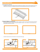
7. INSTALL GEC ATTACH COPPER WIRE Install a minimum 10 AWG solid copper or stranded grounding wire. Torque terminal screw to 20 in-lbs. Grounding Lugs are rated for use with one solid or stranded copper wire, conductor size 10-4AWG. ELECTRICAL DIAGRAM © 2018 IRONRIDGE, INC. VERSION 1.
7. WIRE MANAGEMENT A. PLACE WIRES IN TROUGH Insert microinverter or power optimizer cables into the wire management trough on Mount FX by holding the wire clip up and sliding the cables in. The wire management trough on Mount FX can hold up to one 12mm trunk cable, or two PV cables, or four USE-2 wires. Mount FX utilizes wire clips that maintain tension but do not cause any damage to the surface of wire insulation.
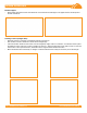
ARRAY MAINTENANCE During the lifetime of a residential rooftop installation, you may need to replace modules or clean the debris that collects underneath the array. Any of these maintenance activities can be carried out through the steps laid out below. Modules can be accessed from both the north and south edges of the array, thus reducing the number of modules that must be detached in order to reach the specific module. A. MODULE REPLACEMENT FROM NORTH EDGE Locate the module that needs to be replaced.
MODULE COMPATIBILITY The FX System may be used to ground and/or mount a PV module complying with UL 1703 only when the specific module has been evaluated for grounding and/or mounting in compliance with the included instructions. Unless otherwise noted, “xxx” refers to the module power rating and both black and silver frames are included in the certification.