
FX Rail-Less Installation
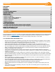

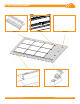
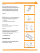
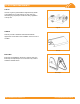
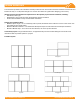
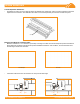
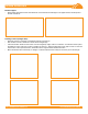

Table Of Contents

FX SYSTEM INSTALLATION MANUAL - 6©
2018 IRONRIDGE, INC. VERSION 1.50
DESIGN GUIDELINES
The information provided in this installation manual provides the end user with the information needed to custom-build and
install a PV array on a composition shingle roof. Use the notes below as a guide when designing your PV array.
Identify structural and mechanical requirements for the specic project and site conditions, including:
• Roof Zones, Roof Type
• Wind Speeds, Snow Loads and other geographically specic information
• Surface Area available for array and PV module information
Spacing and Cantilever Rules:
• Maximum Span Length = 72" for Landscape; 48" for portrait, measured center of Mount to center of next mount. See
span tables for site specic spans.
• Maximum Module Cantilever = 1/3 of Maximum Site Specic Span for both Portrait and Landscape orientations.
• Module to Module Gap = 1/2" in the Cross Roof direction, 3/4" in the Up Roof direction.
Create Array Layout: Using information above, an approximate layout can be created taking into account all of the
obstructions that are present specic to a project.
Possible Layouts:
Portrait
Landscape
Stepped
Hybrid
Staggered